Maytag MAH5500BWW Service Manual - Page 33
Cabinet Vibration Sensor, Cabinet Vibration Absorber, Inertial Unbalance Switch - belt
 |
View all Maytag MAH5500BWW manuals
Add to My Manuals
Save this manual to your list of manuals |
Page 33 highlights
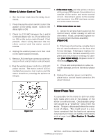
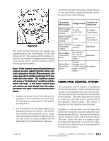
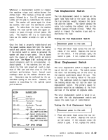
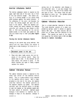
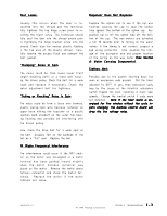
Inertial Unbalance Switch The inertial unbalance switch is located on the upper right hand side of the outer tub, in front of the top concrete weight. The switch consists of a moving weight in the switch body which presses against the switch contacts. If the unbalance of the outer tub becomes too erratic, the moving weight will open the contacts in the switch. When the machine controller senses the switch opening, the machine controller will reduce the spin speed to 650, 550, or 450 rpm depending on the current speed closest to the level spin speed (i.e. 625 rpm trip would drop to 550 rpm) (See Figure 2-12). Testing the Inertial Unbalance Switch: Testing of the switch may prove difficult. The switch will not open unless the switch is moved side to side creating a "G" force of 8 - 9 Ft. lbs. 1 . Disconnect power to the unit. 2 . Place ohm meter leads across the two terminals of the inertial switch. Move the switch side to side. If the contacts do not open easily, the switch is good. If the switch contacts are open or easily tripped, replace the switch. spring rate of the absorber; and changes in the pulley-belt ratio. It can also change from run to run due to the size of the clothes load and type of floor. The sensor finds the optimum speed on every run. The optimum speed is between 750 and 850 rpm. Cabinet Vibration Absorber This is a tuned absorber mounted in the door. The tuned absorber consists of a mass suspended by springs tuned to vibrate at approximately 800 rpm. The mass vibrates 180 degrees out of phase with the vibration of the cabinet. This cancels out much of the vibration caused by the clothes load at 800 rpm (See Section 5: Cabinet Assembly). Cabinet Vibration Sensor The cabinet vibration sensor is mounted to the lower left corner of the machine control board. This is a piezo-electric strip mounted to the machine control board. With a mass attached to the end of the strip, the machine controller monitors the cabinet vibration as the machine reaches top speed. The machine controller uses the vibration sensor to attempt to spin the washer at the optimum speed with the least amount of vibration. Optimum speed changes from machine to machine due to: changes in mass of the absorber; changes in 16008373-01 SECTION 2. ELECTRICAL COMPONENTS & TESTING © 1998 Maytag Corporation 2-13
-
 1
1 -
2
-
3
-
4
-
5
-
6
-
7
-
8
-
9
-
10
-
11
-
12
-
13
-
14
-
15
-
16
-
17
-
18
-
19
-
20
-
21
-
22
-
23
-
24
-
25
-
26
-
27
-
 28
28 -
 29
29 -
 30
30 -
 31
31 -
 32
32 -
 33
33 -
 34
34 -
 35
35 -
 36
36 -
 37
37 -
 38
38 -
39
-
40
-
41
-
42
-
43
-
44
-
45
-
46
-
47
-
48
-
49
-
50
-
51
-
52
-
53
-
54
-
55
-
56
-
57
-
58
-
59
-
60
-
61
-
62
-
63
-
64
-
65
-
66
-
67
-
68
-
69
-
70
-
71
-
72
-
73
-
74
-
75
-
76
-
77
-
78
-
79
-
80
-
81
-
82
-
83
-
84
-
85
-
86
-
87
-
88
-
89
-
90
-
91
-
92
-
93
-
94
-
95
-
96
-
97
-
98
-
99
-
100
-
101
-
102
-
103
-
104
-
105
-
106
-
107
-
108
-
109
-
110
-
111
-
112
-
113
-
114
-
115
-
116
-
117
-
118
-
119
-
120
-
121
-
122
-
123
-
124
-
125
-
126
-
127
-
128
-
129
-
130
-
131
-
132
-
133
-
134
-
135
-
136
-
137
-
138
-
139
-
140
-
141
-
142
-
143
-
144
-
145
-
146
-
147
-
148
-
149
-
150
-
151
-
152
-
153
-
154
-
155
-
156
-
157
 |
 |