Maytag MAH5500BWW Service Manual - Page 54
Cabinet Vibration Absorber, FRONT PANEL, Door Latch Hoop
 |
View all Maytag MAH5500BWW manuals
Add to My Manuals
Save this manual to your list of manuals |
Page 54 highlights
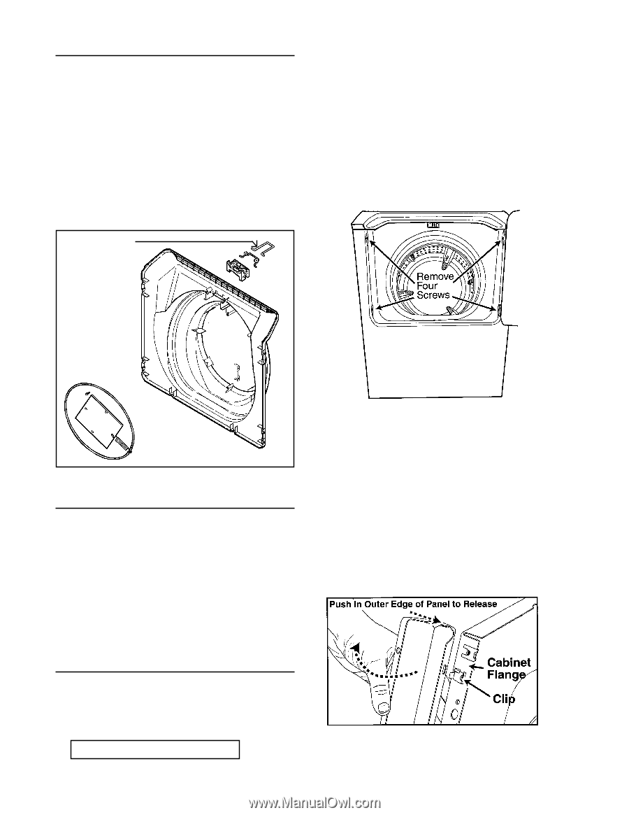
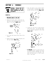
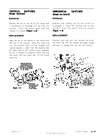
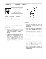
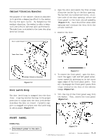
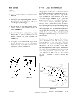
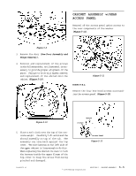
Cabinet Vibration Absorber The purpose of the cabinet vibration absorber is to provide a dampening effect to the washer during the spin cycle. By dampening the machine vibration, the washer is able to maintain and achieve optimum spin performance. The stabilizer is attached to the inner door plug with two screws. 2. Open the door and remove the four screws along the inside lip of the door opening. The two that are located vertically, on either side of the door opening, secure the front panel to the front shroud assembly (Figure 5-3). Care should be taken when opening and closing the door with the screws removed. 3. Remove the door. Door Latch Hoop Inner Door Liner Cabinet Vibration Absorber Figure 5-2 Door Latch Hoop The door latch hoop is snapped into the door liner. A spring retains the hoop in the proper position to align with the door lock mechanism when the door is closed. A plastic support is snapped into place over the latch hoop at add strength (Figure 5-2). Figure 5-3 4. To remove the front panel, open the door, twist the upper right and left panel extensions inward by pressing in on the outer upper edges of the front panel posts. This will disengage the front panel posts from clips located on the face of the cabinet flange (Figure 5-4). 5. Tilt the top of the front panel away from the washer. Then, remove the front panel (Figure 5-4). FRONT PANEL REMOVAL 1. Disconnect power to the unit. 16008373-01 Figure 5-4 © 1998 Maytag Corporation SECTION 5. CABINET ASSEMBLY 5 - 2
-
 1
1 -
2
-
3
-
4
-
5
-
6
-
7
-
8
-
9
-
10
-
11
-
12
-
13
-
14
-
15
-
16
-
17
-
18
-
19
-
20
-
21
-
22
-
23
-
24
-
25
-
26
-
27
-
28
-
29
-
30
-
31
-
32
-
33
-
34
-
35
-
36
-
37
-
38
-
39
-
40
-
41
-
42
-
43
-
44
-
45
-
46
-
47
-
48
-
 49
49 -
 50
50 -
 51
51 -
 52
52 -
 53
53 -
 54
54 -
 55
55 -
 56
56 -
 57
57 -
 58
58 -
 59
59 -
60
-
61
-
62
-
63
-
64
-
65
-
66
-
67
-
68
-
69
-
70
-
71
-
72
-
73
-
74
-
75
-
76
-
77
-
78
-
79
-
80
-
81
-
82
-
83
-
84
-
85
-
86
-
87
-
88
-
89
-
90
-
91
-
92
-
93
-
94
-
95
-
96
-
97
-
98
-
99
-
100
-
101
-
102
-
103
-
104
-
105
-
106
-
107
-
108
-
109
-
110
-
111
-
112
-
113
-
114
-
115
-
116
-
117
-
118
-
119
-
120
-
121
-
122
-
123
-
124
-
125
-
126
-
127
-
128
-
129
-
130
-
131
-
132
-
133
-
134
-
135
-
136
-
137
-
138
-
139
-
140
-
141
-
142
-
143
-
144
-
145
-
146
-
147
-
148
-
149
-
150
-
151
-
152
-
153
-
154
-
155
-
156
-
157
 |
 |