Maytag MAH5500BWW Service Manual - Page 55
Door Lock Mechanism, Top Cover - latch
 |
View all Maytag MAH5500BWW manuals
Add to My Manuals
Save this manual to your list of manuals |
Page 55 highlights
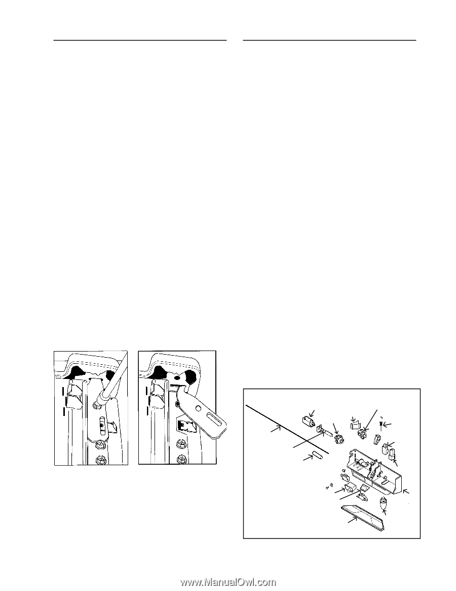
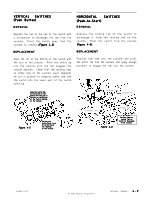
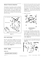
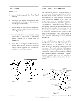
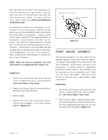
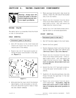
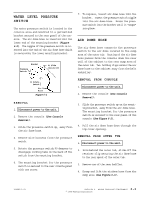
TOP COVER REMOVAL 1. Remove the front panel (See Front Panel Removal). 2. Remove the four screws fastening the dispenser bezel to the top of the top cover (See Dispenser Assembly). 3. Remove two 5/16" hex head screws securing the two hold down brackets on the top cover (Figure 5-5). 4. To remove the hold down brackets, swing the bracket to the outside to unhook the bracket from the slot in the top cover lip (Figure 5-6). 5. If the door is still positioned on the front shroud, open the door prior to lifting the front of the top cover and tilt the top cover toward the rear of the machine. DOOR LOCK MECHANISM The purpose of the door lock mechanism is to secure the door during the spin cycle. When the door is shut, the wire loop on the door engages the rotating gear in the door lock mechanism (Figure 5-7). When the proper water level is reached and the pressure switch is satisfied, 120 VAC is applied to the wax motor. The piston in the wax motor will extend, pushing the latch axle and sliding gear from left to right. Teeth on the face of the sliding gear will intermesh with the teeth on the side of the rotating gear (normally takes about 45-60 seconds). This interlocking of teeth provides the locking action of the lock mechanism. At the end of the spin cycle, when tumbler speed drops below 90 RPM, voltage is no longer applied to the wax motor. The wax motor will cool and relax the piston on the wax motor. The latch axle and sliding gear are then pulled from right to left, disengaging the teeth of the sliding gear from the rotating gear (normally takes 1 - 1½ minutes). This allows the rotating gear to be in a position to rotate if necessary, should the door be opened. Figure 5-5 16008373-01 Figure 5-6 Wax Motor Sliding Gear Rotating Gear Spring Gear Return Spring Accessory Cable Latch Axle Door Lock Switch Axle Spring Lamp Holder Door Switch Ramp Cover Latch Switch Holder Bulb © 1998 Maytag Corporation Figure 5-7 SECTION 5. CABINET ASSEMBLY 5 - 3
-
 1
1 -
2
-
3
-
4
-
5
-
6
-
7
-
8
-
9
-
10
-
11
-
12
-
13
-
14
-
15
-
16
-
17
-
18
-
19
-
20
-
21
-
22
-
23
-
24
-
25
-
26
-
27
-
28
-
29
-
30
-
31
-
32
-
33
-
34
-
35
-
36
-
37
-
38
-
39
-
40
-
41
-
42
-
43
-
44
-
45
-
46
-
47
-
48
-
49
-
 50
50 -
 51
51 -
 52
52 -
 53
53 -
 54
54 -
 55
55 -
 56
56 -
 57
57 -
 58
58 -
 59
59 -
 60
60 -
61
-
62
-
63
-
64
-
65
-
66
-
67
-
68
-
69
-
70
-
71
-
72
-
73
-
74
-
75
-
76
-
77
-
78
-
79
-
80
-
81
-
82
-
83
-
84
-
85
-
86
-
87
-
88
-
89
-
90
-
91
-
92
-
93
-
94
-
95
-
96
-
97
-
98
-
99
-
100
-
101
-
102
-
103
-
104
-
105
-
106
-
107
-
108
-
109
-
110
-
111
-
112
-
113
-
114
-
115
-
116
-
117
-
118
-
119
-
120
-
121
-
122
-
123
-
124
-
125
-
126
-
127
-
128
-
129
-
130
-
131
-
132
-
133
-
134
-
135
-
136
-
137
-
138
-
139
-
140
-
141
-
142
-
143
-
144
-
145
-
146
-
147
-
148
-
149
-
150
-
151
-
152
-
153
-
154
-
155
-
156
-
157
 |
 |