Maytag MAH5500BWW Service Manual - Page 57
Cabinet Assembly W/rear, Access Panel
 |
View all Maytag MAH5500BWW manuals
Add to My Manuals
Save this manual to your list of manuals |
Page 57 highlights
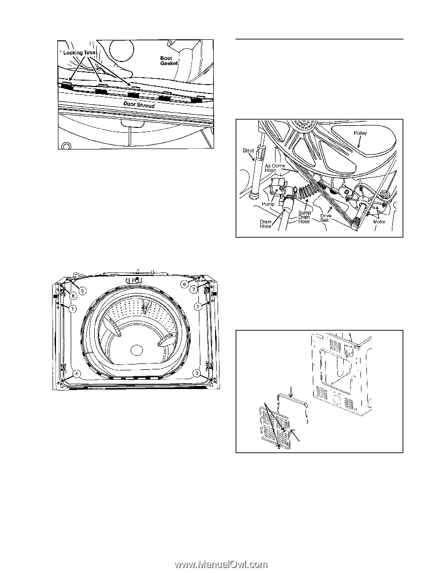
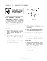
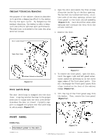
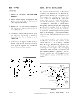
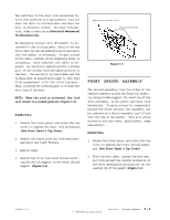
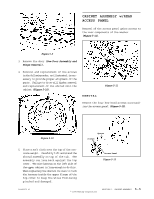
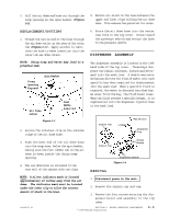
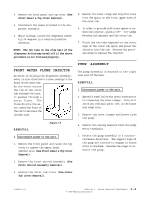
CABINET ASSEMBLY w/REAR ACCESS PANEL Removal of the access panel gains access to the rear components of the washer (Figure 5-11). Figure 5-9 3. Remove the door (See Door Assembly and Hinge Removal). 4. Removal and replacement of the screws in the following order, as illustrated, is necessary to provide proper alignment of the parts. Failure to do so will hinder removal and replacement of the shroud onto the cabinet (Figure 5-10). REMOVAL Figure 5-11 Remove the four hex-head screws surrounding the access panel (Figure 5-12). Figure 5-10 Spacer Screws 5. Place a soft cloth over the top of the concrete weight. Carefully lift and stand the shroud assembly on top of the tub. The assembly can lean back against the top cover. The wire harness on the left side of the upper cabinet is long enough to do this. When replacing the shroud, be sure to tuck the harness inside the upper flange of the top cover to keep the wires from being pinched and damaged. Access Panel Figure 5-12 16008373-01 © 1998 Maytag Corporation SECTION 5. CABINET ASSEMBLY 5 - 5
-
 1
1 -
2
-
3
-
4
-
5
-
6
-
7
-
8
-
9
-
10
-
11
-
12
-
13
-
14
-
15
-
16
-
17
-
18
-
19
-
20
-
21
-
22
-
23
-
24
-
25
-
26
-
27
-
28
-
29
-
30
-
31
-
32
-
33
-
34
-
35
-
36
-
37
-
38
-
39
-
40
-
41
-
42
-
43
-
44
-
45
-
46
-
47
-
48
-
49
-
50
-
51
-
 52
52 -
 53
53 -
 54
54 -
 55
55 -
 56
56 -
 57
57 -
 58
58 -
 59
59 -
 60
60 -
 61
61 -
 62
62 -
63
-
64
-
65
-
66
-
67
-
68
-
69
-
70
-
71
-
72
-
73
-
74
-
75
-
76
-
77
-
78
-
79
-
80
-
81
-
82
-
83
-
84
-
85
-
86
-
87
-
88
-
89
-
90
-
91
-
92
-
93
-
94
-
95
-
96
-
97
-
98
-
99
-
100
-
101
-
102
-
103
-
104
-
105
-
106
-
107
-
108
-
109
-
110
-
111
-
112
-
113
-
114
-
115
-
116
-
117
-
118
-
119
-
120
-
121
-
122
-
123
-
124
-
125
-
126
-
127
-
128
-
129
-
130
-
131
-
132
-
133
-
134
-
135
-
136
-
137
-
138
-
139
-
140
-
141
-
142
-
143
-
144
-
145
-
146
-
147
-
148
-
149
-
150
-
151
-
152
-
153
-
154
-
155
-
156
-
157
 |
 |