Maytag MAH5500BWW Service Manual - Page 66
Outer Tub & Spinner Assembly - door boot
 |
View all Maytag MAH5500BWW manuals
Add to My Manuals
Save this manual to your list of manuals |
Page 66 highlights
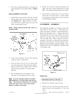
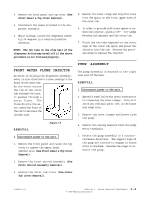
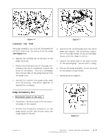
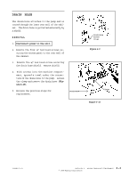
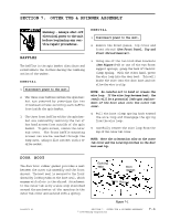
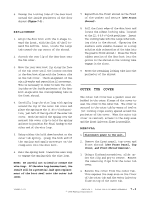
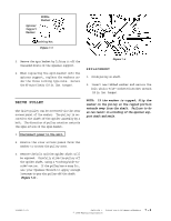
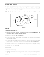
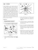
SECTION 7. OUTER TUB & SPINNER ASSEMBLY Warning - Always shut off electrical power to the unit before beginning any service repair procedures. BAFFLES The baffles in the spin basket distribute and redistribute the clothes during the tumbling action of the washer. REMOVAL 1. Disconnect power to the unit. 2. The three rear baffles within the spin basket are removed by removing the two crosshead screws securing each baffle from inside the spin basket. 3. The three front baffles within the spin basket are removed by removing the two ¼" hex head screws from outside of the spin basket. To gain access, remove the outer tub cover. The front baffle mounting screws can now be reached through the sump area, using a flat ratchet with a ¼" drive socket. REMOVAL 1. Disconnect power to the unit. 2. Remove the front panel, top cover and front shroud (See Front Panel, Top and Front Shroud Removal). 3. Using one of the two hold down brackets (See Figure 5-6) or one of the two front support springs, grasp the hook of the boot clamp spring. With the other hand, press the wire loop into the door boot. This will brake the wire into the door boot and not allow the wire to slip. NOTE: Be careful not to bend or crease the wire loop. If the wire loop becomes bent, the result will be a potential leak upon replacement of the boot seal onto the outer tub cover. 4. Pull the boot clamp spring hook toward the wire loop and disengage the spring from the wire loop. 5. Carefully remove the wire loop from the lip of the outer tub cover. NOTE: Note the orientation ribs on the outer tub cover and the locating notches in the door boot seal lip. DOOR BOOT The door boot rubber gasket provides a seal between the outer tub assembly and the front shroud. The boot seal is secured to the front shroud by locking tabs on the boot seal, which engage with slots in the shroud. Attachment to the outer tub is by a wire loop stretched around the perimeter of the opening in the outer tub cover and secured with a spring. Locking Tabs Boot Gasket Door Shroud 16008373-01 Figure 7-1 SECTION 7. OUTER TUB & SPINNER ASSEMBLY © 1998 Maytag Corporation 7-1
-
 1
1 -
2
-
3
-
4
-
5
-
6
-
7
-
8
-
9
-
10
-
11
-
12
-
13
-
14
-
15
-
16
-
17
-
18
-
19
-
20
-
21
-
22
-
23
-
24
-
25
-
26
-
27
-
28
-
29
-
30
-
31
-
32
-
33
-
34
-
35
-
36
-
37
-
38
-
39
-
40
-
41
-
42
-
43
-
44
-
45
-
46
-
47
-
48
-
49
-
50
-
51
-
52
-
53
-
54
-
55
-
56
-
57
-
58
-
59
-
60
-
 61
61 -
 62
62 -
 63
63 -
 64
64 -
 65
65 -
 66
66 -
 67
67 -
 68
68 -
 69
69 -
 70
70 -
 71
71 -
72
-
73
-
74
-
75
-
76
-
77
-
78
-
79
-
80
-
81
-
82
-
83
-
84
-
85
-
86
-
87
-
88
-
89
-
90
-
91
-
92
-
93
-
94
-
95
-
96
-
97
-
98
-
99
-
100
-
101
-
102
-
103
-
104
-
105
-
106
-
107
-
108
-
109
-
110
-
111
-
112
-
113
-
114
-
115
-
116
-
117
-
118
-
119
-
120
-
121
-
122
-
123
-
124
-
125
-
126
-
127
-
128
-
129
-
130
-
131
-
132
-
133
-
134
-
135
-
136
-
137
-
138
-
139
-
140
-
141
-
142
-
143
-
144
-
145
-
146
-
147
-
148
-
149
-
150
-
151
-
152
-
153
-
154
-
155
-
156
-
157
 |
 |