Maytag MAH5500BWW Service Manual - Page 68
Spin Basket Assembly, W/balance Ring - repair parts
 |
View all Maytag MAH5500BWW manuals
Add to My Manuals
Save this manual to your list of manuals |
Page 68 highlights
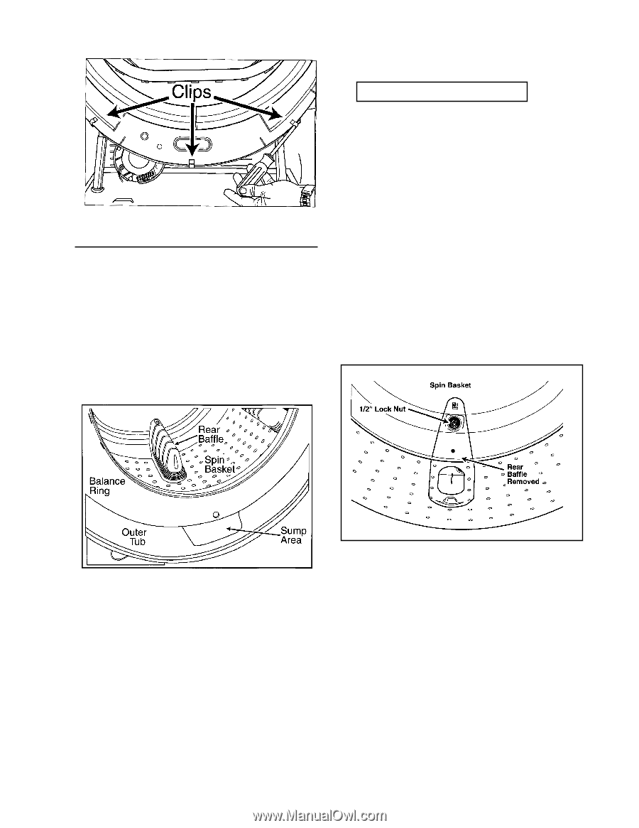
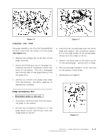
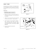
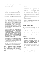
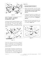
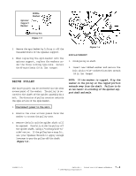
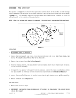
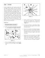
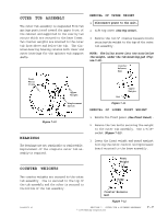
REMOVAL 1. Disconnect power to the unit. 2. Remove the front panel, top cover, front shroud, outer tub cover and rear baffles (See Front Panel, Top cover, Front Shroud, Outer Tub Cover and Rear Baffle Removal). Figure 7-2 SPIN BASKET ASSEMBLY w/BALANCE RING The balance ring is securely fastened to the spin basket and cannot be obtained as a separate repair part. To obtain, order complete spin basket assembly. The balance ring is filled with a calcium chloride solution and baffles. 3. To separate the spinner tub support from the spinner, remove the three rear baffles within the spin basket by removing the two screws securing each baffle (See Baffle Removal). 4. Remove the three locking type nuts (½" socket) securing the spin basket to the spider assembly (Figure 7-5). Figure 7-3 Figure 7-4 within the ring allow the fluid to disperse within the ring evenly. By rotating the spin basket, you can hear the fluid dispersing within the baffles of the balance ring. This sound is normal. The spin basket is mounted to the spinner support by means of threaded studs on the support extending through the spin basket and secured with nuts. The mounting nuts are concealed under the rear baffles (Figure 7-4). 16008373-01 SECTION 7. OUTER TUB & SPINNER ASSEMBLY © 1998 Maytag Corporation 7-3
-
 1
1 -
2
-
3
-
4
-
5
-
6
-
7
-
8
-
9
-
10
-
11
-
12
-
13
-
14
-
15
-
16
-
17
-
18
-
19
-
20
-
21
-
22
-
23
-
24
-
25
-
26
-
27
-
28
-
29
-
30
-
31
-
32
-
33
-
34
-
35
-
36
-
37
-
38
-
39
-
40
-
41
-
42
-
43
-
44
-
45
-
46
-
47
-
48
-
49
-
50
-
51
-
52
-
53
-
54
-
55
-
56
-
57
-
58
-
59
-
60
-
61
-
62
-
 63
63 -
 64
64 -
 65
65 -
 66
66 -
 67
67 -
 68
68 -
 69
69 -
 70
70 -
 71
71 -
 72
72 -
 73
73 -
74
-
75
-
76
-
77
-
78
-
79
-
80
-
81
-
82
-
83
-
84
-
85
-
86
-
87
-
88
-
89
-
90
-
91
-
92
-
93
-
94
-
95
-
96
-
97
-
98
-
99
-
100
-
101
-
102
-
103
-
104
-
105
-
106
-
107
-
108
-
109
-
110
-
111
-
112
-
113
-
114
-
115
-
116
-
117
-
118
-
119
-
120
-
121
-
122
-
123
-
124
-
125
-
126
-
127
-
128
-
129
-
130
-
131
-
132
-
133
-
134
-
135
-
136
-
137
-
138
-
139
-
140
-
141
-
142
-
143
-
144
-
145
-
146
-
147
-
148
-
149
-
150
-
151
-
152
-
153
-
154
-
155
-
156
-
157
 |
 |