Maytag MAH5500BWW Service Manual - Page 7
General Information - parts
 |
View all Maytag MAH5500BWW manuals
Add to My Manuals
Save this manual to your list of manuals |
Page 7 highlights
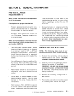
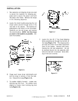
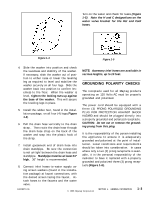
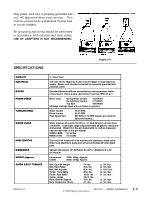
SECTION 1. GENERAL INFORMATION PRE-INSTALLATION REQUIREMENTS NOTE: Proper installation is the responsibility of the purchaser. Checkpoints for proper installation: • Properly grounded electrical outlet is required. Use 15 amp fuse or compatible circuit breaker for electrical service. • Standpipe Drain System must accept 1½" O.D. drain hose. Standpipe height of 36" is recommended. NOTE: If drain standpipe is in excess of 5 feet above floor level, install pump accessory kit, part number 22002136. • This unit is not equipped with a siphon break, and the drain hose must be elevated to a minimum height of 24". A 36" high standpipe is recommended. For all installations the drain hose must be supported by the drain hose strap on the back of the washer. • Hot and Cold water faucets must be within four (4) feet of the back of the washer. This allows quick access for immediate water shut off. • Water heater should be set to deliver a minimum of 120ºF (49º C) hot water to the washer. • Do not store or operate washer in temperatures below freezing. This can cause damage to the pump, hoses and other components. cause an extended fill time. Refer to the troubleshooting section for more information regarding a solution for slow fill situations. • Best performance is obtained with the washer installed on a solid floor. Wood floor constructions may need to be reinforced to minimize vibration from unbalanced load situations. Carpets and soft tile surfaces are also contributing factors to vibration and/or movement during the spin cycle. Never install washer on a platform or weak support structure. UNCRATING INSTRUCTIONS NOTE: The following steps must be performed in the correct order to ease uncrating. 1. Remove the carton by cutting only in marked areas of the carton. CAUTION: Hoses are connected to the washer. 2. Carefully remove any packaging materials from the outside of the washer. IMPORTANT: DO NOT cut the red straps securing the power cord and inlet hoses at this time. They will be removed later during installation. 3. Remove the accessory package from inside the tub. 4. Remove the crate bottom from the washer by removing crate bottom wire clips. • Water pressure of 20 - 120 P.S.I. is required to fill the washer in the appropriate time frame. Pressures of less than 20 P.S.I. may 16008373-01 © 1998 Maytag Corporation SECTION 1. GENERAL INFORMATION 1-1
-
 1
1 -
 2
2 -
 3
3 -
 4
4 -
 5
5 -
 6
6 -
 7
7 -
 8
8 -
 9
9 -
 10
10 -
 11
11 -
 12
12 -
13
-
14
-
15
-
16
-
17
-
18
-
19
-
20
-
21
-
22
-
23
-
24
-
25
-
26
-
27
-
28
-
29
-
30
-
31
-
32
-
33
-
34
-
35
-
36
-
37
-
38
-
39
-
40
-
41
-
42
-
43
-
44
-
45
-
46
-
47
-
48
-
49
-
50
-
51
-
52
-
53
-
54
-
55
-
56
-
57
-
58
-
59
-
60
-
61
-
62
-
63
-
64
-
65
-
66
-
67
-
68
-
69
-
70
-
71
-
72
-
73
-
74
-
75
-
76
-
77
-
78
-
79
-
80
-
81
-
82
-
83
-
84
-
85
-
86
-
87
-
88
-
89
-
90
-
91
-
92
-
93
-
94
-
95
-
96
-
97
-
98
-
99
-
100
-
101
-
102
-
103
-
104
-
105
-
106
-
107
-
108
-
109
-
110
-
111
-
112
-
113
-
114
-
115
-
116
-
117
-
118
-
119
-
120
-
121
-
122
-
123
-
124
-
125
-
126
-
127
-
128
-
129
-
130
-
131
-
132
-
133
-
134
-
135
-
136
-
137
-
138
-
139
-
140
-
141
-
142
-
143
-
144
-
145
-
146
-
147
-
148
-
149
-
150
-
151
-
152
-
153
-
154
-
155
-
156
-
157
 |
 |