Maytag MAH5500BWW Service Manual - Page 72
Outer Tub Assembly, Bearings, Counter Weights - bearing replacement
 |
View all Maytag MAH5500BWW manuals
Add to My Manuals
Save this manual to your list of manuals |
Page 72 highlights
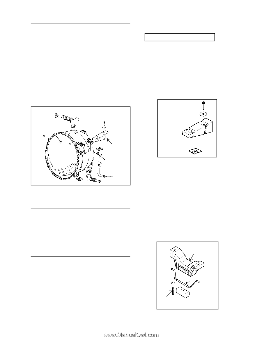
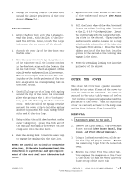
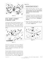
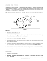
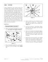
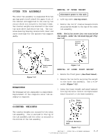
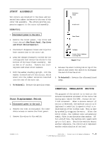
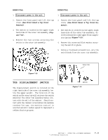
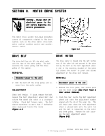
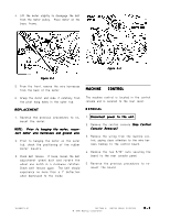
OUTER TUB ASSEMBLY The outer tub assembly is suspended from two springs positioned toward the upper front of the cabinet and supported in the rear by two struts which are secured to the base frame. Two counter weights are mounted to the outer tub from above and below the tub. The aluminum bearing housing retains both inner and outer bearings for the spinner tub support shafts. REMOVAL OF UPPER WEIGHT 1. Disconnect power to the unit. 2. Lift top cover (See Top Cover). 3. Remove the two ½" counter balance bolts securing the weight to the top of the outer tub assembly. NOTE: The bolts screw into two nuts below the weight, under the tub mounting pad (Figure 7-11). Counter Balance Bolt Front Water Flume Upper Weight Displacement Switch Upper Weight Nut Figure 7-11 REMOVAL OF LOWER FRONT WEIGHT Figure 7-10 BEARINGS The bearings are not repairable or replaceable. Replacement of the complete outer tub assembly is required. COUNTER WEIGHTS 1. Remove the front panel (See Front Panel). 2. Remove the two bolts securing the weight to the outer tub assembly. Use a 9/16" socket (Figure 7-12). 3. Lower the front weight and guard against hitting the motor control microprocessor board mounted to the base assembly. Front Weight Two counter weights are secured to the outer tub assembly. One is secured to the top of the tub assembly and the other is secured to the bottom of the tub assembly. Strap Counter Balance Bolt Figure 7-12 16008373-01 SECTION 7. OUTER TUB & SPINNER ASSEMBLY © 1998 Maytag Corporation 7-7
-
 1
1 -
2
-
3
-
4
-
5
-
6
-
7
-
8
-
9
-
10
-
11
-
12
-
13
-
14
-
15
-
16
-
17
-
18
-
19
-
20
-
21
-
22
-
23
-
24
-
25
-
26
-
27
-
28
-
29
-
30
-
31
-
32
-
33
-
34
-
35
-
36
-
37
-
38
-
39
-
40
-
41
-
42
-
43
-
44
-
45
-
46
-
47
-
48
-
49
-
50
-
51
-
52
-
53
-
54
-
55
-
56
-
57
-
58
-
59
-
60
-
61
-
62
-
63
-
64
-
65
-
66
-
 67
67 -
 68
68 -
 69
69 -
 70
70 -
 71
71 -
 72
72 -
 73
73 -
 74
74 -
 75
75 -
 76
76 -
 77
77 -
78
-
79
-
80
-
81
-
82
-
83
-
84
-
85
-
86
-
87
-
88
-
89
-
90
-
91
-
92
-
93
-
94
-
95
-
96
-
97
-
98
-
99
-
100
-
101
-
102
-
103
-
104
-
105
-
106
-
107
-
108
-
109
-
110
-
111
-
112
-
113
-
114
-
115
-
116
-
117
-
118
-
119
-
120
-
121
-
122
-
123
-
124
-
125
-
126
-
127
-
128
-
129
-
130
-
131
-
132
-
133
-
134
-
135
-
136
-
137
-
138
-
139
-
140
-
141
-
142
-
143
-
144
-
145
-
146
-
147
-
148
-
149
-
150
-
151
-
152
-
153
-
154
-
155
-
156
-
157
 |
 |