Maytag MAH5500BWW Service Manual - Page 78
Motor, Control
 |
View all Maytag MAH5500BWW manuals
Add to My Manuals
Save this manual to your list of manuals |
Page 78 highlights
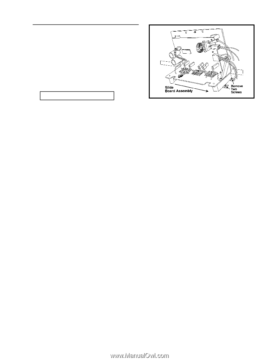
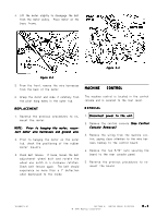
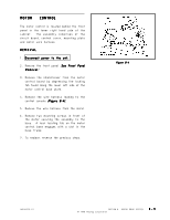
MOTOR CONTROL The motor control is located behind the front panel in the lower right hand side of the cabinet. The assembly comprises of the circuit board, control cover, mounting plate and motor wire harness. REMOVAL 1 . Disconnect power to the unit. 2 . Remove the front panel (See Front Panel Removal). 3 . Remove the shield/cover from the motor control board by depressing the locking tab found along the lower left side of the motor control base plate. 4. Remove the wire harness leading to the control console (Figure 8-4). 5 . Remove the wire harness from the motor. 6 . Remove two mounting screws in front of the motor securing the assembly to the base. A rear locating tab on the motor control base engages with a slot in the base frame. 7 . To replace, reverse the previous steps. Figure 8-4 16008373-01 SECTION 8. MOTOR DRIVE SYSTEM © 1998 Maytag Corporation 8-3
-
 1
1 -
2
-
3
-
4
-
5
-
6
-
7
-
8
-
9
-
10
-
11
-
12
-
13
-
14
-
15
-
16
-
17
-
18
-
19
-
20
-
21
-
22
-
23
-
24
-
25
-
26
-
27
-
28
-
29
-
30
-
31
-
32
-
33
-
34
-
35
-
36
-
37
-
38
-
39
-
40
-
41
-
42
-
43
-
44
-
45
-
46
-
47
-
48
-
49
-
50
-
51
-
52
-
53
-
54
-
55
-
56
-
57
-
58
-
59
-
60
-
61
-
62
-
63
-
64
-
65
-
66
-
67
-
68
-
69
-
70
-
71
-
72
-
 73
73 -
 74
74 -
 75
75 -
 76
76 -
 77
77 -
 78
78 -
 79
79 -
 80
80 -
 81
81 -
 82
82 -
 83
83 -
84
-
85
-
86
-
87
-
88
-
89
-
90
-
91
-
92
-
93
-
94
-
95
-
96
-
97
-
98
-
99
-
100
-
101
-
102
-
103
-
104
-
105
-
106
-
107
-
108
-
109
-
110
-
111
-
112
-
113
-
114
-
115
-
116
-
117
-
118
-
119
-
120
-
121
-
122
-
123
-
124
-
125
-
126
-
127
-
128
-
129
-
130
-
131
-
132
-
133
-
134
-
135
-
136
-
137
-
138
-
139
-
140
-
141
-
142
-
143
-
144
-
145
-
146
-
147
-
148
-
149
-
150
-
151
-
152
-
153
-
154
-
155
-
156
-
157
 |
 |