Maytag MEC7430WB Installation Instructions - Page 4
Installation Instructions - electric cooktop
 |
View all Maytag MEC7430WB manuals
Add to My Manuals
Save this manual to your list of manuals |
Page 4 highlights
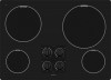
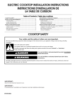
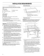
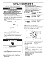
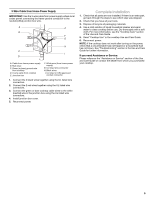
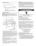
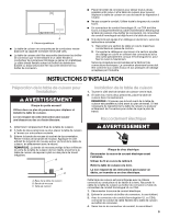
INSTALLATION INSTRUCTIONS Prepare Cooktop for Installation WARNING Excessive Weight Hazard Use two or more people to move and install cooktop. 2. Remove junction box cover, if present. 3. Connect the flexible cable conduit from the cooktop to the junction box using a UL listed or CSA approved conduit connector. 4. Tighten screws on conduit connector if present. 5. See "Electrical Connection Options" chart to complete installation for your type of electrical connection. Electrical Connection Options Failure to do so can result in back or other injury. 1. Decide on the final location for the cooktop. 2. Using 2 or more people, place the cooktop upside down on a covered surface. 3. Remove foam strip from literature packing. Remove backing from foam strip. Apply foam strip adhesive-side down around bottom of cooktop, flush with edge. NOTE: The foam strip keeps debris from the underside of the cooktop glass and helps the cooktop sit flat on uneven counters. A B If your home has: 4-wire 5" (12.7 cm) 3-wire 3¹⁄₂" (8.9 cm) And you will be Go to Section: connecting to: A fused disconnect or circuit breaker box 4-Wire Cable from Home Power Supply A fused disconnect or circuit breaker box 3-Wire Cable from Home Power Supply C 4-Wire Cable from Home Power Supply A. Cooktop base B. Foam strip C. Cooktop IMPORTANT: Use the 4-wire cable from home power supply where local codes do not permit connecting the frame-ground conductor to the neutral (white) junction box wire: Install Cooktop 1. Using 2 or more people, turn cooktop right side up. 2. Place cooktop in cutout. NOTE: Make sure that the front edge of the cooktop is parallel to the front edge of the countertop. If repositioning is needed, lift entire cooktop up from cutout to avoid scratching the countertop. Make Electrical Connection WARNING A B E F G C H D I A. Cable from home power supply B. Red wires C. Green or bare ground wires D. 3-wire cable from cooktop E. Junction box F. White wire (from home power supply) G. UL listed wire connector H. Black wires I. UL listed or CSA approved conduit connector Electrical Shock Hazard Disconnect power before servicing. Use 8 gauge copper wire. Electrically ground cooktop. Failure to follow these instructions can result in death, fire, or electrical shock. This cooktop is manufactured with the frame connected to the bare ground wire. Connect the cooktop cable to the junction box through the UL listed or CSA approved conduit connector. 1. Disconnect power. 1. Connect the 2 black wires together using the UL listed wire connectors. 2. Connect the 2 red wires together using the UL listed wire connectors. 3. Connect the green (or bare) ground wire from the cooktop cable to the green (or bare) ground wire (in the junction box) using the UL listed wire connectors. 4. Put a UL listed wire connector on the end of the white wire. NOTE: Do not connect the bare ground wire to the neutral (white) wire in the junction box. 5. Install junction box cover. 6. Reconnect power. 4
-
 1
1 -
 2
2 -
 3
3 -
 4
4 -
 5
5 -
 6
6 -
 7
7 -
 8
8 -
 9
9 -
 10
10 -
11
-
12
-
13
-
14
-
15
-
16
 |
 |