Maytag MEDB955FW Dimension Guide
Maytag MEDB955FW Manual
 |
View all Maytag MEDB955FW manuals
Add to My Manuals
Save this manual to your list of manuals |
Maytag MEDB955FW manual content summary:
- Maytag MEDB955FW | Dimension Guide - Page 1
Gas and Electric Dryer PRODUCT MODEL NUMBERS MEDB955F, MGDB955F INSTALLATION CLEARANCES For each arrangement, consider allowing more space for ease of installation and servicing, spacing for companion appliances and clearances for walls, doors, and floor moldings. Space must be large enough to - Maytag MEDB955FW | Dimension Guide - Page 2
gas must be used. An individual manual shutoff valve must be installed within 6 ft (1.8 m) of the dryer in accordance with the National Fuel Gas Code ANSI Z223.1. ELECTRICAL REQUIREMENTS - Gas complete details, see Installation Instructions packed with product. Specifications subject to change without
-
 1
1 -
 2
2
 |
 |
Gas and Electric Dryer
PRODUCT MODEL NUMBERS
W10884084A
05/2016
MEDB955F, MGDB955F
Spacing for recessed area or closet installation
The dimensions shown are for the recommended spacing
allowed.
■
Additional spacing should be considered for ease of
installation and servicing.
■
Additional clearances might be required for wall, door, and
floor moldings.
■
Additional spacing of 1" (25 mm) on all sides of the dryer is
recommended to reduce noise transfer.
■
For closet installation, with a door, minimum ventilation
openings in the top and bottom of the door are required.
Louvered doors with equivalent ventilitation openings are
acceptable.
■
Companion appliance spacing should also be considered.
Minimum Required Spacing
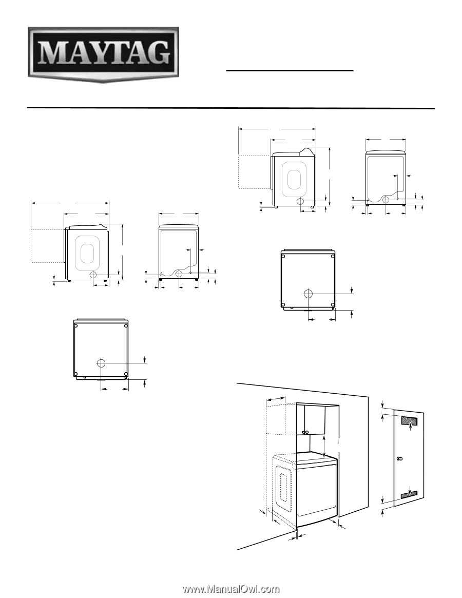
DRYER DIMENSIONS
INSTALLATION CLEARANCES
For each arrangement, consider allowing more space for ease of
installation and servicing, spacing for companion appliances and
clearances for walls, doors, and floor moldings. Space must be
large enough to allow door to fully open. Add spacing on all sides
of dryer to reduce noise transfer. If a closet door or louvered door
is installed, top and bottom air openings in door are required.
NOTE:
Most installations require a minimum of 6" (152 mm)
clearance behind dryer for exhaust vent with elbow. See
“Venting Requirements.”
Bottom view:
8
1
/
2
"
(218 mm)
14
3
/
8
"
(365 mm)
41
3
/
8
"
(1050 mm)
3
5
/
8
"
(93 mm)
1"
(25 mm)
33
1
/
2
"
(851 mm)
57
5
/
8
"
(1464 mm)
11
3
/
8
"
(289 mm)
Door Opened
Door Closed
5
7
/
8
"
(150 mm)
3
1
/
2
"
(93 mm)
4
1
/
2
"
(115 mm)
3"
(77 mm)
29"
(737 mm)
14
1
/
2
"
(370 mm)
1
3
/
8
"
(35 mm)
Back view
Side view
Front Controls Models
Bottom view:
8
1
/
2
"
(218 mm)
14
3
/
8
"
(365 mm)
3
5
/
8
"
(93 mm)
1"
(25 mm)
33
1
/
2
"
(851 mm)
57
5
/
8
"
(1464 mm)
11
3
/
8
"
(289 mm)
Door Opened
Door Closed
5
7
/
8
"
(150 mm)
3
1
/
2
"
(93 mm)
4
1
/
2
"
(115 mm)
3"
(77 mm)
29"
(737 mm)
14
1
/
2
"
(370 mm)
1
3
/
8
"
(35 mm)
Back view
Side view
Rear Controls Models
43
7
∕
16
"
(1103 mm)
6"/0"
(152 mm/0 mm)
14" max
(356 mm)
1"/0"
(25 mm/0 mm)
1"/1"
(25 mm)
18"/18"*
(457 mm)
3"/3"
(76 mm)
3"/3"
(76 mm)
(310 cm
2
)
(155 cm
2
)
Recommended/Minimum spacing
Companion appliance spacing should also be considered.
24 in.±/24 in.±
48 in.±/48 in.±