Maytag MEDE500VW Installation Instructions
Maytag MEDE500VW - Performance Series 27 Inch Electric Dryer Manual
 |
UPC - 883049135670
View all Maytag MEDE500VW manuals
Add to My Manuals
Save this manual to your list of manuals |
Maytag MEDE500VW manual content summary:
- Maytag MEDE500VW | Installation Instructions - Page 1
POWER HOOKUP 5 Electrical Requirements 5 Electrical Connection 6 VENTING 11 Venting Requirements 11 Plan Vent System 12 Install Vent System 13 INSTALL LEVELING LEGS 13 CONNECT VENT 14 CONNECT INLET HOSE (STEAM MODELS 14 LEVEL DRYER 15 COMPLETE INSTALLATION 15 TROUBLESHOOTING 15 DRYER - Maytag MEDE500VW | Installation Instructions - Page 2
: Do not use leveling legs supplied with dryer if installing on a pedestal. Parts needed Check local codes. Check existing electrical supply and venting. See "Electrical Requirements" and "Venting Requirements" before purchasing parts. Mobile home installations require metal exhaust system hardware - Maytag MEDE500VW | Installation Instructions - Page 3
proper exhaust installation. See "Venting Requirements." ■ A separate 30-amp circuit. ■ If you are using a power supply cord, a grounded electrical outlet located within 2 ft (610 mm) of either side of the dryer. See "Electrical Requirements." ■ A sturdy floor to support the total dryer weight of - Maytag MEDE500VW | Installation Instructions - Page 4
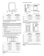
door with vents Steam (Electric or Gas) Non-Steam (Electric or Gas) A* 1" (25 mm) 1" (25 mm) B 32 9/16" (827 mm) 31 1/2" (800 mm) C** 5" (127 mm) 5" (127 mm) *Required spacing **For side or bottom venting, 0" (0 mm) spacing is allowed. Recessed or closet installation - Dryer on pedestal - Maytag MEDE500VW | Installation Instructions - Page 5
/NFPA 70latest edition and all local codes and ordinances. The National Electrical Code requires a 4-wire power supply connection for homes built after 1996, dryer circuits involved in remodeling after 1996, and all mobile home installations. A copy of the above code standards can be obtained from - Maytag MEDE500VW | Installation Instructions - Page 6
new branch-circuit installations, (2) mobile homes, (3) recreational vehicles, and (4) areas where local codes prohibit grounding through the neutral conductors. If using a power supply cord: Use a UL listed power supply cord kit marked for use with clothes dryers. The kit should contain: ■ A UL - Maytag MEDE500VW | Installation Instructions - Page 7
ground wire B. External ground conductor screw C. Center, silver-colored terminal block screw D. Terminal block cover and hold-down screw 3. Install strain relief. Style 1: Power supply cord strain relief ■ Remove the screws from a 3/4" (19 mm) UL listed strain relief (UL marking on strain relief - Maytag MEDE500VW | Installation Instructions - Page 8
wire cable. 4-wire connection: Power supply cord IMPORTANT: A 4-wire connection is required for mobile homes and where local codes do not permit the use of 3-wire connections. A B F 4. Now complete installation following instructions for your type of electrical connection: 4-wire (recommended - Maytag MEDE500VW | Installation Instructions - Page 9
(green or bare) of power supply cord C. ¾" (19 mm dryer rear panel. Secure cover with hold-down screw. 7. You have completed your electrical connection. Now go to "Venting Requirements." 4-wire connection: Direct wire IMPORTANT: A 4-wire connection is required for mobile homes and where local codes - Maytag MEDE500VW | Installation Instructions - Page 10
tab of terminal block cover into slot of dryer rear panel. Secure cover with hold-down screw. 7. You have completed your electrical connection. Now go to "Venting Requirements." 3-wire connection: Power supply cord Use where local codes permit connecting cabinet-ground conductor to neutral wire - Maytag MEDE500VW | Installation Instructions - Page 11
of terminal block cover into slot of dryer rear panel. Secure cover with hold-down screw. 6. You have completed your electrical connection. Now go to "Venting Requirements." Optional 3-wire connection Use for direct wire or power supply cord where local codes do not permit connecting cabinet-ground - Maytag MEDE500VW | Installation Instructions - Page 12
or bushes, snow line, etc.). A. Dryer B. Elbow C. Wall D. Exhaust hood H E. Clamps F. Rigid metal or flexible metal vent G. Vent length necessary to connect elbows H. Exhaust outlet Optional exhaust installations This dryer can be converted to exhaust out the right side, left side, or through the - Maytag MEDE500VW | Installation Instructions - Page 13
the life of the dryer. ■ Reduce performance, resulting in longer drying times and increased energy usage. The vent system chart provides venting requirements that will help to achieve the best drying performance. Vent system chart NOTE: Side and bottom exhaust installations have a 90º turn inside - Maytag MEDE500VW | Installation Instructions - Page 14
washer cold inlet hose to other end of "Y" connector. Screw on coupling by hand until it is seated on connector. A CONNECT VENT 1. Using a 4" (102 mm) clamp, connect vent to exhaust outlet in dryer. If connecting to existing vent, make sure the vent is clean. The dryer vent must fit over the dryer - Maytag MEDE500VW | Installation Instructions - Page 15
electrical supply is connected. ■ Household fuse is intact and tight, or circuit breaker has not tripped. ■ Dryer door is closed. This dryer automatically runs an installation diagnostic routine at the start of its first cycle. If you receive an L2 code, there may be a problem with your home power - Maytag MEDE500VW | Installation Instructions - Page 16
breakers. Replace the fuse or reset the circuit breaker. Confirm the power cord is properly installed. Refer to "Electrical Connection" for details. Select a Timed Dry heated cycle, and restart the dryer. If the message persists, consult a qualified electrician. ■ "AF" (low airflow condition): The
-
 1
1 -
 2
2 -
 3
3 -
 4
4 -
 5
5 -
 6
6 -
 7
7 -
8
-
9
-
10
-
11
-
12
-
13
-
14
-
15
-
16
 |
 |

ELECTRIC DRYER INSTALLATION INSTRUCTIONS
U.S.A. ONLY
Para una versión de estas instrucciones en español, visite www.Whirlpool.com
TABLE OF CONTENTS
DRYER SAFETY
..............................................................................
1
INSTALLATION REQUIREMENTS
................................................
2
Tools and Parts
............................................................................
2
Optional Equipment
.....................................................................
3
Location Requirements
................................................................
3
ELECTRIC DRYER POWER HOOKUP
.........................................
5
Electrical Requirements
...............................................................
5
Electrical Connection
...................................................................
6
VENTING
.......................................................................................
11
Venting Requirements
................................................................
11
Plan Vent System
.......................................................................
12
Install Vent System
.....................................................................
13
INSTALL LEVELING LEGS
...........................................................
13
CONNECT VENT
...........................................................................
14
CONNECT INLET HOSE
(STEAM MODELS)
........................................................................
14
LEVEL DRYER
..............................................................................
15
COMPLETE INSTALLATION
.......................................................
15
TROUBLESHOOTING
..................................................................
15
W10255468C
W10259190B - SP
DRYER SAFETY
You
You can be killed or seriously injured if you don't immediately
can be killed or seriously injured if you don't
follow
All
s
afety me
ss
age
s
will tell you what the potential hazard i
s
, tell you how to reduce the chance of injury, and tell you what can
happen if the in
s
truction
s
are not followed.
Your safety and the safety of others are very important.
We have provided many important
s
afety me
ss
age
s
in thi
s
manual and on your appliance. Alway
s
read and obey all
s
afety
me
ss
age
s
.
Thi
s
i
s
the
s
afety alert
s
ymbol.
Thi
s
s
ymbol alert
s
you to potential hazard
s
that can kill or hurt you and other
s
.
All
s
afety me
ss
age
s
will follow the
s
afety alert
s
ymbol and either the word “DANGER” or “WARNING.”
The
s
e word
s
mean:
follow instructions.
instructions.
DANGER
WARNING