Maytag MEDE500W Installation Instructions
Maytag MEDE500W - Performance 27" Electric Dryer Manual
 |
UPC - 883049186665
View all Maytag MEDE500W manuals
Add to My Manuals
Save this manual to your list of manuals |
Maytag MEDE500W manual content summary:
- Maytag MEDE500W | Installation Instructions - Page 1
14 CONNECT INLET HOSE (STEAM MODELS 14 LEVEL DRYER 15 COMPLETE INSTALLATION 15 TROUBLESHOOTING 15 DRYER SAFETY Your safety and the safety of others are very important. We have provided many important safety messages in this manual and on your appliance. Always read and obey all safety messages - Maytag MEDE500W | Installation Instructions - Page 2
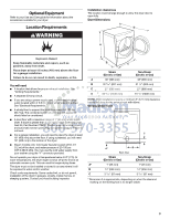
hose D. Long inlet hose E. Rubber washer Remove parts package from dryer drum. Check that all parts are included. NOTE: Do not use leveling legs supplied with dryer if installing on a pedestal. 4 Leveling legs Remove parts package from dryer drum. Check that all parts are included. NOTE: Do not - Maytag MEDE500W | Installation Instructions - Page 3
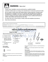
sturdy floor to support the total dryer weight of 200 lbs (90.7 kg). The combined weight of a companion appliance should also be considered. ■ A level floor with a maximum slope of 1" (25 mm) under entire dryer. If slope is greater than 1" (25 mm), install Extended Dryer Feet Kit, Part Number 279810 - Maytag MEDE500W | Installation Instructions - Page 4
servicing. ■ Additional clearances might be required for wall, door, and floor moldings. ■ Additional spacing should be considered on all sides of the dryer appliance spacing should also be considered. Custom undercounter installation - Dryer or closet installation - Dryer on pedestal (460 mm) A - Maytag MEDE500W | Installation Instructions - Page 5
is allowed. Recommended installation spacing for recessed or closet installation, with stacked washer and dryer The dimensions shown are for the recommended spacing. 48 in.2 * (310 Title 24, HUD Part 280) or Standard CAN/CSA-Z240 MH. Mobile home installations require: All Dryers: ■ Metal exhaust - Maytag MEDE500W | Installation Instructions - Page 6
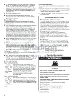
connection you will be using and follow the instructions provided for it here. ■ This dryer is manufactured ready to install with a 3-wire . ■ A 4-wire power supply connection must be used when the appliance is installed in a location where grounding through the neutral conductor is prohibited - Maytag MEDE500W | Installation Instructions - Page 7
Be sure that the wire insulation on the power supply cord is inside the strain relief. The strain relief should have a tight fit with the dryer cabinet and be in a horizontal position. Do not further tighten strain relief screws at this point. Style 2: Direct wire strain relief WARNING Fire Hazard - Maytag MEDE500W | Installation Instructions - Page 8
3-wire connections. A B F 4. Now complete installation following instructions for your type of electrical connection: 4-wire (recommended) 3-wire NEMA Type 14-30R) A UL listed, 120/ 240-volt minimum, 30-amp, dryer power supply cord* 4-wire connection: Power supply cord 4-wire direct 5" (127 mm - Maytag MEDE500W | Installation Instructions - Page 9
relief screws. 6. Insert tab of terminal block cover into slot of dryer rear panel. Secure cover with hold-down screw. 7. You have completed 3-wire connections. Direct wire cable must have 5 ft (1.52 m) of extra length so dryer can be moved if needed. Strip 5" (127 mm) of outer covering from end of - Maytag MEDE500W | Installation Instructions - Page 10
: Direct wire Use where local codes permit connecting cabinet-ground conductor to neutral wire. Direct wire cable must have 5 ft (1.52 m) of extra length so dryer can be moved if needed. Strip 31/2" (89 mm) of outer covering from end of cable. Strip insulation back 1" (25 mm). If using 3-wire cable - Maytag MEDE500W | Installation Instructions - Page 11
instructions can result in death or fire. WARNING: To reduce the risk of fire, this dryer MUST BE EXHAUSTED OUTDOORS. IMPORTANT: Observe all governing codes and ordinances. The dryer . ■ Review vent system chart. Modify existing vent system if necessary to achieve the best drying performance. Only - Maytag MEDE500W | Installation Instructions - Page 12
■ Flexible metal vent must be fully extended and supported when the dryer is in its final location. ■ Remove excess problems and health problems. Plan Vent System Choose your exhaust installation type Recommended exhaust installations Typical installations vent the dryer from the rear of the dryer - Maytag MEDE500W | Installation Instructions - Page 13
manufacturer's instructions. A Service" section to order. ■ Over-the-Top Installation: Part Number 4396028 ■ Periscope Installation (For use with dryer vent to wall vent mismatch): Part Number 4396037 - 0" (0 mm) to 18" (457 mm) mismatch Part elbows needed for best drying performance ■ Use the - Maytag MEDE500W | Installation Instructions - Page 14
seated on fill valve connector. CONNECT INLET HOSE (STEAM MODELS) The dryer must be connected to the cold water faucet using the new inlet hoses. Do not use old hoses. 1. Turn cold water faucet off and remove washer inlet hose. 2. Remove old rubber washer from inlet hose and replace with new rubber - Maytag MEDE500W | Installation Instructions - Page 15
performance. Excessive scale buildup may lead to the need for certain part replacement or repair. All Models: 13. Select a Timed Dry heated cycle, and start the dryer. Do not select the Air Only Temperature setting. If the dryer will not start, check the following: ■ Controls are set in a running - Maytag MEDE500W | Installation Instructions - Page 16
Variable (E1, E2, E3) service codes: Call for service. Dryer Results Clothes are not drying satisfactorily, drying times are too long, or load dryer requires a minimum of 1" (25 mm) of airspace, and, for most installations, the rear of the dryer requires 5" (127 mm). See the Installation Instructions
-
 1
1 -
 2
2 -
 3
3 -
 4
4 -
 5
5 -
 6
6 -
 7
7 -
8
-
9
-
10
-
11
-
12
-
13
-
14
-
15
-
16
 |
 |

ELECTRIC DRYER INSTALLATION INSTRUCTIONS
U.S.A. ONLY
Para una versión de estas instrucciones en español, visite www.Whirlpool.com
TABLE OF CONTENTS
DRYER SAFETY
..............................................................................
1
INSTALLATION REQUIREMENTS
................................................
2
Tools and Parts
............................................................................
2
Optional Equipment
.....................................................................
3
Location Requirements
................................................................
3
ELECTRIC DRYER POWER HOOKUP
.........................................
5
Electrical Requirements
...............................................................
5
Electrical Connection
...................................................................
6
VENTING
.......................................................................................
11
Venting Requirements
................................................................
11
Plan Vent System
.......................................................................
12
Install Vent System
.....................................................................
13
INSTALL LEVELING LEGS
...........................................................
13
CONNECT VENT
...........................................................................
14
CONNECT INLET HOSE
(STEAM MODELS)
........................................................................
14
LEVEL DRYER
..............................................................................
15
COMPLETE INSTALLATION
.......................................................
15
TROUBLESHOOTING
..................................................................
15
W10255468C
W10259190B - SP
DRYER SAFETY
You
You can be killed or seriously injured if you don't immediately
can be killed or seriously injured if you don't
follow
All
s
afety me
ss
age
s
will tell you what the potential hazard i
s
, tell you how to reduce the chance of injury, and tell you what can
happen if the in
s
truction
s
are not followed.
Your safety and the safety of others are very important.
We have provided many important
s
afety me
ss
age
s
in thi
s
manual and on your appliance. Alway
s
read and obey all
s
afety
me
ss
age
s
.
Thi
s
i
s
the
s
afety alert
s
ymbol.
Thi
s
s
ymbol alert
s
you to potential hazard
s
that can kill or hurt you and other
s
.
All
s
afety me
ss
age
s
will follow the
s
afety alert
s
ymbol and either the word “DANGER” or “WARNING.”
The
s
e word
s
mean:
follow instructions.
instructions.
DANGER
WARNING