Maytag MEDE500WR Installation Instructions
Maytag MEDE500WR Manual
 |
UPC - 883049186689
View all Maytag MEDE500WR manuals
Add to My Manuals
Save this manual to your list of manuals |
Maytag MEDE500WR manual content summary:
- Maytag MEDE500WR | Installation Instructions - Page 1
LEGS 13 CONNECT VENT 14 CONNECT INLET HOSE (STEAM MODELS 14 LEVEL DRYER 15 COMPLETE INSTALLATION 15 TROUBLESHOOTING 15 DRYER SAFETY Your safety and the safety of others are very important. We have provided many important safety messages in this manual and on your appliance. Always read and - Maytag MEDE500WR | Installation Instructions - Page 2
exhaust vent) ■ Tin snips (new vent installations) ■ ¼" nut driver (recommended) ■ Tape measure ■ Pliers Parts supplied Non-Steam Models Steam Models A B C D E A. Leveling legs (4) B. "Y" connector C. Short inlet hose D. Long inlet hose E. Rubber washer Remove parts package from dryer drum - Maytag MEDE500WR | Installation Instructions - Page 3
sturdy floor to support the total dryer weight of 200 lbs (90.7 kg). The combined weight of a companion appliance should also be considered. ■ A level floor with a maximum slope of 1" (25 mm) under entire dryer. If slope is greater than 1" (25 mm), install Extended Dryer Feet Kit, Part Number 279810 - Maytag MEDE500WR | Installation Instructions - Page 4
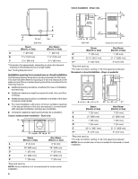
appliance spacing should also be considered. Custom undercounter installation - Dryer models are not recommended for undercounter installation. 4 A* B C** Side view Closet door with vents bottom venting, 0" (0 mm) spacing is allowed. Recessed or closet installation - Dryer on pedestal (460 - Maytag MEDE500WR | Installation Instructions - Page 5
686 mm) I 1" (25 mm) 1" (25 mm) *Required spacing **For side or bottom venting, 0" (0 mm) spacing is allowed. Recommended installation spacing for recessed or closet installation, with stacked washer and dryer The dimensions shown are for the recommended spacing. 48 in.2 * (310 cm2) 3"* (76 mm - Maytag MEDE500WR | Installation Instructions - Page 6
using and follow the instructions provided for it here. ■ This dryer is manufactured ready to install with a 3-wire appliance is installed in a location where grounding through the neutral conductor is prohibited. Grounding through the neutral is prohibited for (1) new branch-circuit installations - Maytag MEDE500WR | Installation Instructions - Page 7
colored terminal block screw D. Terminal block cover and hold-down screw 3. Install strain relief. Style 1: Power supply cord strain relief ■ Remove the screws relief. The strain relief should have a tight fit with the dryer cabinet and be in a horizontal position. Do not further tighten strain - Maytag MEDE500WR | Installation Instructions - Page 8
of 3-wire connections. A B F 4. Now complete installation following instructions for your type of electrical connection: 4-wire (recommended) circuit breaker box* A UL listed, 120/ 240-volt minimum, 30-amp, dryer power supply cord* 4-wire connection: Direct Wire 3-wire connection: Power supply - Maytag MEDE500WR | Installation Instructions - Page 9
strain relief screws. 6. Insert tab of terminal block cover into slot of dryer rear panel. Secure cover with hold-down screw. 7. You have completed your electrical connection. Now go to "Venting Requirements." 4-wire connection: Direct wire IMPORTANT: A 4-wire connection is required for mobile - Maytag MEDE500WR | Installation Instructions - Page 10
5. Tighten strain relief screw. 6. Insert tab of terminal block cover into slot of dryer rear panel. Secure cover with hold-down screw. 7. You have completed your electrical connection. Now go to "Venting Requirements." 3-wire connection: Power supply cord Use where local codes permit connecting - Maytag MEDE500WR | Installation Instructions - Page 11
vent. Do not use a plastic vent. Do not use a metal foil vent. Failure to follow these instructions can result in death or fire. WARNING: To reduce the risk of fire, this dryer metal foil vent with rigid heavy metal vent or flexible metal vent. ■ Review vent system chart. Modify existing vent system - Maytag MEDE500WR | Installation Instructions - Page 12
, paint, wallpaper, carpets, etc. Housecleaning problems and health problems. Plan Vent System Choose your exhaust installation type Recommended exhaust installations Typical installations vent the dryer from the rear of the dryer. Other installations are possible. B C Good Better D Clamps - Maytag MEDE500WR | Installation Instructions - Page 13
for purchase. Please see the "Assistance or Service" section to order. ■ Over-the-Top Installation: Part Number 4396028 ■ Periscope Installation (For use with dryer vent to wall vent mismatch): Part Number 4396037 - 0" (0 mm) to 18" (457 mm) mismatch Part Number 4396011 - 18" (457 mm) to 29 - Maytag MEDE500WR | Installation Instructions - Page 14
washer cold inlet hose to other end of "Y" connector. Screw on coupling by hand until it is seated on connector. A CONNECT VENT 1. Using a 4" (102 mm) clamp, connect vent to exhaust outlet in dryer. If connecting to existing vent, make sure the vent is clean. The dryer vent must fit over the dryer - Maytag MEDE500WR | Installation Instructions - Page 15
door is closed. This dryer automatically runs an installation diagnostic routine at the start of its first cycle. If you receive an L2 code, there may be a problem with your home power supply keeping the dryer's heater from turning on. See "Troubleshooting." 14. When the dryer has been running for - Maytag MEDE500WR | Installation Instructions - Page 16
(25 mm) of airspace, and, for most installations, the rear of the dryer requires 5" (127 mm). See the Installation Instructions. Fire Hazard Use a heavy metal vent. Do not use a plastic vent. Do not use a metal foil vent. Failure to follow these instructions can result in death or fire. W10255468C
-
 1
1 -
 2
2 -
 3
3 -
 4
4 -
 5
5 -
 6
6 -
 7
7 -
8
-
9
-
10
-
11
-
12
-
13
-
14
-
15
-
16
 |
 |

ELECTRIC DRYER INSTALLATION INSTRUCTIONS
U.S.A. ONLY
Para una versión de estas instrucciones en español, visite www.Whirlpool.com
TABLE OF CONTENTS
DRYER SAFETY
..............................................................................
1
INSTALLATION REQUIREMENTS
................................................
2
Tools and Parts
............................................................................
2
Optional Equipment
.....................................................................
3
Location Requirements
................................................................
3
ELECTRIC DRYER POWER HOOKUP
.........................................
5
Electrical Requirements
...............................................................
5
Electrical Connection
...................................................................
6
VENTING
.......................................................................................
11
Venting Requirements
................................................................
11
Plan Vent System
.......................................................................
12
Install Vent System
.....................................................................
13
INSTALL LEVELING LEGS
...........................................................
13
CONNECT VENT
...........................................................................
14
CONNECT INLET HOSE
(STEAM MODELS)
........................................................................
14
LEVEL DRYER
..............................................................................
15
COMPLETE INSTALLATION
.......................................................
15
TROUBLESHOOTING
..................................................................
15
W10255468C
W10259190B - SP
DRYER SAFETY
You
You can be killed or seriously injured if you don't immediately
can be killed or seriously injured if you don't
follow
All
s
afety me
ss
age
s
will tell you what the potential hazard i
s
, tell you how to reduce the chance of injury, and tell you what can
happen if the in
s
truction
s
are not followed.
Your safety and the safety of others are very important.
We have provided many important
s
afety me
ss
age
s
in thi
s
manual and on your appliance. Alway
s
read and obey all
s
afety
me
ss
age
s
.
Thi
s
i
s
the
s
afety alert
s
ymbol.
Thi
s
s
ymbol alert
s
you to potential hazard
s
that can kill or hurt you and other
s
.
All
s
afety me
ss
age
s
will follow the
s
afety alert
s
ymbol and either the word “DANGER” or “WARNING.”
The
s
e word
s
mean:
follow instructions.
instructions.
DANGER
WARNING