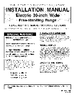
Maytag MER5775RAB Installation Manual
Maytag MER5775RAB - Ceramic Range Manual
 |
View all Maytag MER5775RAB manuals
Add to My Manuals
Save this manual to your list of manuals |
Maytag MER5775RAB manual content summary:
- Maytag MER5775RAB | Installation Manual - Page 1
Electric 30-inch Wide Free-stand" e PLEASE KEEP THIS MANUAL FOR FUTURE REFERENCE THE MANUAL IS INTENDED TO ASSIST IN THE INITIAL INSTALLATION AND ADJUSTMENTS OF THE RANGE. Only qualified personnel should install or service this range. Read "Safety Instructions" in Use & Care book before using - Maytag MER5775RAB | Installation Manual - Page 2
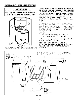
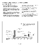
located above the surface units should be avoided. If cabinet storage is to be provided, the risk can be reduced by installing a range hood that projects horizontally a minimum of 5 inches (13 cm) beyond the bottom of the cabinets. FIGURE 1 1, 2, 3 - COMBUSTIBLE BUILDING WALLS. 4 - COMBUSTIBLE WALL - Maytag MER5775RAB | Installation Manual - Page 3
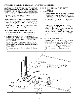
of range tip-over exists if the appliance is not installed in accordance with the provided installation instructions. The proper use of this device minimizes the risk of TIP-OVER. In using this device the consumer must still observe the safety precautions as stated in the USE and CARE MANUAL and - Maytag MER5775RAB | Installation Manual - Page 4
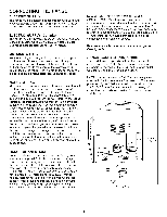
ANTI-TIP DEVICE INSTALLATION INSTRUCTIONS STEP 3 - Range Installation A. For safety considerations as well as optimum performance, adjust the range so it is level and to desired height prior to installing in cabinet opening. Levelness may be checked by placing a spirit level or a large pan - Maytag MER5775RAB | Installation Manual - Page 5
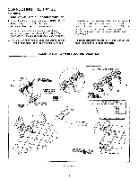
pronged plug at the opposite end. RANGE CONNECTIONS Some models are shipped direct from the factory with service cords (pigtails) attached. There are no range connections necessary on these models. Just plug into the range outlet. On models not provided with a service cord, connection to the power - Maytag MER5775RAB | Installation Manual - Page 6
post of the main terminal connection block and the range chassis. 2. If bare copper or aluminum wiring is used, attach adapter lugs as shown in figure 6. (See Bare Wire Connection). Torque specifications are shown below. 3. The middle wire of the service cord or ground lead of 3-wire conduit MUST - Maytag MER5775RAB | Installation Manual - Page 7
plate. Conversion From 3-Wire To 4-Wire Service (Free-standing Model With 3-Wire Service Cord Attached), Disconnect range from power. Remove the access cover on back of range and remove the 3-wire service cord from the main terminal block. Follow instructions as outlined in figure 7 to connect the - Maytag MER5775RAB | Installation Manual - Page 8
individual de 30 pulg 76.2 cm) de ancho CONSERVE ESTE MANUAL PARA REFERENCIA FUTURA EL MANUAL TIENE LA FINALIDAD DE AYUDARLE EN LA INSTALACION Y AJUSTES Titulo 24 CFR, Parte 3280 (anteriormente Federal Standard for Mobile Home Construction and Safety, Titulo 24 HUD, Parte 280)) o, cuando - Maytag MER5775RAB | Installation Manual - Page 9
UNA SUPERFICIE ADYACENTE. "A" = 30" (76.2 CM) - 31" (78.7 CM) PARA CANADA "B" = 3 1/4" (8.3 CM) - 3 314" (9.5 CM) PAPA CANADa, 36" (9! .5 CM) ALTURA DE LA PARTE SUPERIOR DEL MOSTRADOR ,_A _ ABERTUPAS SUPERIOR E INFERIOR DEL GABINETE TOMACORRIENTE DE 120/208 VOLTIOS, 120/240 VOLTIOS AL RAS POR CADA - Maytag MER5775RAB | Installation Manual - Page 10
reduce el riesgo de LADEO. AI usar este dispositivo el consumidor aun debe acatar las precauciones de seguridad que se dictan en el MANUAL DE USO Y CUIDADO y debe evitar utilizar las puertas del horno come banquillo. Las instrucciones de instalacion se proporcionan para madera y cemento tanto en - Maytag MER5775RAB | Installation Manual - Page 11
superior principal o por el protector posterior o el asa de la puerta. Todas las estufas individuales con la parte superior de vidrio tienen la parte superior fija. La parte superior del serpentin se puede levantar. a. Alinee la estufa en su ubicacion final y preparela para deslizarla hacia atras - Maytag MER5775RAB | Installation Manual - Page 12
asegQrese de que todas las conexiones electricas esten bien ajustadas y coloque todas las cubiertas. Quite la cubierta de acceso del bloque terminal de la parte posterior de la estufa. (Vea la figura 5). CONEXIONES DE LA ESTUFA (en Canada) Este modelo se embarc6 directamente de fabrica con el cordon - Maytag MER5775RAB | Installation Manual - Page 13
CONEXION DE LA ESTUFA FIGURA 6 INSTALACION DEL CORDON DE SERVICIO DE 3 CABLES O DEL CONDUCTOR Verifigue que la tira de conexion a tierra de cobre ESTE CONECTADA entre el poste medic del bloque de conexi6n del terminal principal y del bastidor de la estufa. . Si se usa alambrado desnudo de cobre o - Maytag MER5775RAB | Installation Manual - Page 14
Modelo individual con cordon sujeto de servicio de 3 cables) Desconecte la estufa de la energia electrica. Quite la cubierta de acceso en la parte posterior de la estufa y quite el cord6n de servicio de 3 cables del bloque del terminal principal. Siga las instrucciones a continuacion segQn se indica - Maytag MER5775RAB | Installation Manual - Page 15
INSTRUCTIONS AVEC L'APPAREIL MAN U EL D E M VEUILLEZ CONSERVER CE MANUEL POUR R#FI_RENCE ULTI_RIEURE CE MANUEL EST DESTINE A FACILITER LA MISE EN SERVICE ET LE REGLAGE INITIAUX DE LA CUISINIERE. La mise en service est adjacente a des armoires pouvant supporter une temperature inferieure a 194°F ( - Maytag MER5775RAB | Installation Manual - Page 16
de brQlure ou d'incendie en essayant d'atteindre un objet place au-dessus d'elements brQlants, eviter d'avoir un espace de rangement au-dessus de la table de sont en materiau combustible. REMARQUE : DANS LE CAS D'UNE MISE EN SERVICE AU CANADA, UNE CUISINIERE AMOVIBLE NE DOlT PAS ETRE PLACEE .&.MOINS - Maytag MER5775RAB | Installation Manual - Page 17
cuisiniere risque de basculer si elle n'est pas mise en place conformement aux instructions fournies. Si le support est utilise correctement, il reduit le risque que la cuisiniere ne BASCULE. M6me si le support est utilise correctement, le consommateur doit observer les precautions indiquees dans le - Maytag MER5775RAB | Installation Manual - Page 18
ont un dessus non relevable. Si elles sont equipees d'elements chauffants tubulaires, le dessus est relevable. Pour verifier le la cuisiniere et le pied de mise a niveau qui va s'inserer dans le support de stabilisation (voir figure 4). Attention : La cuisiniere peut se trouver aMmee - Maytag MER5775RAB | Installation Manual - Page 19
(en kW). ALIMENTATION I_LECTRIQUE (Canada) Lors de la mise en service, la cuisiniere doit _tre installee conformement aux normes ACN STD.C22.1 la cuisiniere. 11suffit de brancher la fiche dans la prise murale. D'autres modeles ne sont pas munis d'un cordon d'alimentation et dans ce cas, le - Maytag MER5775RAB | Installation Manual - Page 20
cosse correspondante tel qu'indiqu& Les couples sont indiques ci-dessous. 4. Placer la retenue mecanique a bride sur le dessus de la plaque support de gaine tel qu'indique et serrer la bride sur le cordon d'alimentation ou la gaine. INSTALLATION ACCEPTABLE - FICHE .,&T. ROIS FILS CONNEXION A_FILS - Maytag MER5775RAB | Installation Manual - Page 21
3 FILS A UNE INSTALLATION 4 FILS (Modeles amovibles avec cordon d'alimentation en place) Debrancher 3 ills du bornier. Suivre les instructions donnees a la figure 7 pour connecter 20 PO-LB LISER AVEC UNE ,# GAINE. ENLEVER LE (_, SUPPORT, RETOURNER ET FIXER A NOUVEAU AVEC LE PETIT TROU VISIBLE.
-
 1
1 -
 2
2 -
 3
3 -
 4
4 -
 5
5 -
 6
6 -
 7
7 -
8
-
9
-
10
-
11
-
12
-
13
-
14
-
15
-
16
-
17
-
18
-
19
-
20
-
21
 |
 |
INSTALLER:
LEAVE
THESE
INSTRUCTIONS
WITH
THE APPLIANCE
ON
MANUAl
IN
Electric
30-inch
Wide
Free-stand"
PLEASE
KEEP
THIS
MANUAL
e
FOR
FUTURE
REFERENCE
THE MANUAL
IS INTENDED
TO ASSIST
IN THE INITIAL
INSTALLATION
AND ADJUSTMENTS
OF
THE RANGE.
Only
qualified
personnel
should
install or service
this
range.
Read
"Safety
Instructions"
in Use
&
Care book before
using
range.
Improper
installation,
adjustment,
alteration,
service,
maintenance
or
use of range
can
result
in serious
injury
or property
damage.
CAUTION:
This range
has been designed
in
accordance
with the requirements
of various
safety
agencies
and complies
with the maximum
allowable
wood
cabinet
temperatures
of
194°F.
tf this
range is
installed
with
cabinets
that have a lower working
temperature
than 194°F,
discoloration,
delamination
or melting
may occur.
ENGLISH
0
PP.
1-7
ESPANOL
0
pag.
8-14
FRAN(_AIS
i$
p. 15-21
CLEARANCE
DIMENSIONS
For complete
information
in regard to installation of
freestanding
range, see figures
1 and 2 on page 2. For
SAFETY
CONSIDERATIONS
do not install a range in
any combustible
cabinetry which is not in accord with the
installation clearances
shown in figure 1.
MOBILE
HOMES
The installation of a range designed for mobile home
installation must conform with the Manufactured
Home
Construction
and Safety Standard, Title 24 CFR, Part
3280 (formerly
the Federal Standard for Mobile Home
Construction
and Safety, Title 24 HUD, Part 280) or,
when such standard
is not applicable,
the Standard for
Manufactured
Home Installations
1982 (Manufactured
Home Sites, Communities
and Set-Ups), ANSI
A225.1-1atest edition, or with local codes.
LOCATING
THE
RANGE
Place range in a well lit area. Do not set range over
holes in the floor or other locations where
it may be
subject to strong drafts. Any opening
in the wall behind
the range and in the floor under the range should be
sealed.
Make sure the flow of cooling/ventilation
air is
not obstructed
below the range.
8101 P506-60
(06-03-00)