Maytag MEW9530AS Installation Guide
Maytag MEW9530AS Manual
 |
View all Maytag MEW9530AS manuals
Add to My Manuals
Save this manual to your list of manuals |
Maytag MEW9530AS manual content summary:
- Maytag MEW9530AS | Installation Guide - Page 1
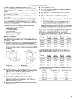
Parts 2 Location Requirements 2 Electrical Requirements 5 INSTALLATION INSTRUCTIONS 6 Prepare Built-In Oven 6 Remove Oven Door 6 Positioning Oven BUILT-IN OVEN SAFETY Your safety and the safety of others are very important. We have provided many important safety messages in this manual and on - Maytag MEW9530AS | Installation Guide - Page 2
is required. See "Electrical Requirements" section. ■ Electrical supply junction box should be located 3" (7.6 cm) maximum below the support surface when the oven is installed in a wall cabinet. A 1" (2.5 cm) minimum diameter hole should have been drilled in the right rear or left rear corner of - Maytag MEW9530AS | Installation Guide - Page 3
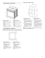
height G. 24" (60.7 cm) cutout depth NOTE: The cutout height can be between 26 68.4 cm) and 29 74.8 cm) for single ovens. E D C 27" (68.6 cm) models A. 27" (68.6 cm) min. cabinet width B. 1¹⁄₂" (3.8 cm) min. top of cutout to underside of countertop C. 5¹⁄₄" (13.3 cm) bottom of cutout to floor - Maytag MEW9530AS | Installation Guide - Page 4
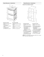
Product Dimensions - Double Ovens B Cabinet Dimensions - Double Ovens Double Ovens Installed in Cabinet A A C B D F E D 27" (68.6 cm) models A. 51 130.0 cm) max. overall height B. 25 64.6 cm) max. recessed width C. 48 124.0 cm) recessed height D. 23¹⁄₄" (59.1 cm) max. recessed depth E. 27" - Maytag MEW9530AS | Installation Guide - Page 5
is for serviceability of the oven. ■ A Canadian Electrical Code, Part 1 and C22.2 oven, you must determine the type of electrical connection you will be using and follow the instructions A Single Oven Double Oven A. Model/serial number plate A. Model/serial number plate ■ Models rated from 7.3 - Maytag MEW9530AS | Installation Guide - Page 6
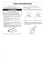
. 4. Remove the hardware package from inside the bag containing literature. 5. Remove and set aside racks and other parts from inside the oven. 6. If installing a single oven below a cooktop, remove the adhesive backing from the foam strip and press it to the back of the control panel. NOTE: When - Maytag MEW9530AS | Installation Guide - Page 7
Feet for Multiple Cabinet Cutout Heights Single Ovens The positioning of the oven feet allow a single oven to be installed in a cutout height between 26 68.4 cm) and 29 74.8 cm). Refer to the following instructions to position the feet for the size of your cabinet cutout. 2. Remove the foot from - Maytag MEW9530AS | Installation Guide - Page 8
side of the foot is positioned toward the top of the oven. Double Ovens The positioning of the oven feet allow a double oven to be installed in a cutout height between 48⁷⁄₈" (124.1 cm) and 52 132.6 cm). Refer to the following instructions to position the feet for the size of your cabinet cutout - Maytag MEW9530AS | Installation Guide - Page 9
a front foot on the left front spacer using a #8-18 x ³⁄₈" screw. NOTE: Position the foot so the long side of the foot is facing toward the oven as shown. 7. Go to the "Make Electrical Connection" section. Cutout Height is between 51 130.0 cm) and 52 132.6 cm) 1. Using 2 or more people, place - Maytag MEW9530AS | Installation Guide - Page 10
Connection" section. Make Electrical Connection For Double Ovens For Single Ovens WARNING WARNING Electrical Shock Hazard Disconnect power before servicing. Use 8 gauge solid copper wire. Electrically ground oven. Failure to follow these instructions can result in death, fire, or electrical - Maytag MEW9530AS | Installation Guide - Page 11
CSA approved conduit connector to the junction box. A A. UL listed or CSA approved conduit connector 5. Route the flexible conduit from the oven to the junction box through a UL listed or CSA approved conduit connector. 6. Tighten screws on conduit connector. 7. See "Electrical Connection Options - Maytag MEW9530AS | Installation Guide - Page 12
grommet. Do not overtighten screws. 6. On models with the foot positioned with the long side of the foot facing toward the top of the oven, the oven vent is taped to the side of the oven. See the following instructions to install. ■ Align vent tab (B) with oven frame (A) as shown. ■ Using one #8-18 - Maytag MEW9530AS | Installation Guide - Page 13
briefly, and "PF" should appear in the display. 16. If the display panel does not light, reference the "Assistance or Service" section of the Use and Care Guide or contact the dealer from whom you purchased your oven. C A. #8-18 x ¹⁄₄" screw B. Bottom vent trim C. Vent ■ Align vent tab (B) with - Maytag MEW9530AS | Installation Guide - Page 14
available. For more information, read the Use and Care Guide. 3. Press BROIL on single oven models. NOTE: Press UPPER BROIL or LOWER BROIL on double oven models. 4. Set the temperature. ■ See "Troubleshooting" section in the Use and Care Guide. 6. When oven has been on for 5 minutes, feel for heat - Maytag MEW9530AS | Installation Guide - Page 15
Notes 15 - Maytag MEW9530AS | Installation Guide - Page 16
Notes 16 - Maytag MEW9530AS | Installation Guide - Page 17
est le danger potentiel et vous disent comment réduire le risque de blessure et ce qui peut se produire en cas de non-respect des instructions. EXIGENCES D'INSTALLATION Outillage et pièces Rassembler les outils et composants nécessaires avant d'entreprendre l'installation. Lire et observer les - Maytag MEW9530AS | Installation Guide - Page 18
doit avoir été percé dans l'angle arrière gauche ou droit de la surface de support pour le passage du câble d'alimentation de l'appareil jusqu'au boîtier de connexion étiquette d'homologation placée sur le dessus. Voir les E instructions d'installation du plan de travail au sujet des dimensions de - Maytag MEW9530AS | Installation Guide - Page 19
Fours simples installés dans un placard A Dimensions du produit - Fours doubles. B B D F G E C A C Modèles de 27" (68,6 cm) A. Largeur du placard 27" (68,6 cm) min. B. 1" (2,5 cm) entre le sommet de l'ouverture découpée et le bas de la porte du placard supérieur C. 32" (81,3 cm) entre le bas de - Maytag MEW9530AS | Installation Guide - Page 20
44131-5575 Raccordement électrique Pour installer le four correctement, il faut établir le type de raccords électriques que l'on utilisera et suivre les instructions indiquées ici. ■ Le four doit être alimenté par une source d'électricité appropriée (caractéristiques de tension et fréquence spécifi - Maytag MEW9530AS | Installation Guide - Page 21
■ L'installateur doit fournir un connecteur de conduit (homologation UL ou CSA). ■ Si le domicile est équipé d'un câblage en aluminium, suivre les instructions suivantes : 1. Connecter une section de câble en cuivre massif aux conducteurs en queue de cochon. 2. Connecter le câblage en aluminium à la - Maytag MEW9530AS | Installation Guide - Page 22
pour déplacer et installer le four. Le non-respect de cette instruction peut causer une blessure au dos ou d'autre blessure. Dépose de de matériel à l'intérieur du sachet de documentation. 5. Enlever et conserver à part les grilles et autres composants qu'on trouve à l'intérieur du four. 6. Si - Maytag MEW9530AS | Installation Guide - Page 23
, on peut installer un four simple dans une cavité d'encastrement d'une hauteur comprise entre 26 68,4 cm) et 29 74,8 cm). Consulter les instructions suivantes pour adapter la position des pieds à la taille de la cavité d'encastrement. 2. Retirer le pied de la cale d'espacement avant droite en - Maytag MEW9530AS | Installation Guide - Page 24
peut installer un four double dans une cavité d'encastrement d'une hauteur comprise entre 48⁷⁄₈" (124,1 cm) et 52 132,6 cm). Consulter les instructions suivantes pour adapter la position des pieds à la taille de la cavité d'encastrement. La hauteur de la cavité d'encastrement est comprise entre 48 - Maytag MEW9530AS | Installation Guide - Page 25
La hauteur de la cavité d'encastrement est comprise entre 50¹⁄₂" (128,2 cm) et 51¹⁄₈" (129,9 cm) 1. À l'aide d'au moins 2 personnes, placer le four sur sa partie arrière, sur une surface couverte. 6. À l'aide d'au moins 2 personnes, placer le four en position verticale. 2. Installer un pied sur la - Maytag MEW9530AS | Installation Guide - Page 26
avant d'entreprendre le travail. Utiliser du fil en cuivre rigide de calibre 12. Relier le four à la terre. Le non-respect de ces instructions peut causer un décès, un incendie ou un choc électrique. Le câblage d'alimentation de ce four comporte un conducteur neutre (blanc) et un conducteur - Maytag MEW9530AS | Installation Guide - Page 27
5. Acheminer le conduit de câble flexible depuis le four jusqu'au boîtier de connexion - utiliser un connecteur de conduit (homologation UL ou CSA). 6. Serrer les vis sur le connecteur de conduit. 7. Voir "Tableau des options de raccordement électrique" pour terminer l'installation correspondant à - Maytag MEW9530AS | Installation Guide - Page 28
par du ruban adhésif. Pour l'installation, procéder selon les instructions suivantes. ■ Aligner le support de l'évent (B) avec le châssis du four (A) comme illustré. ■ Avec une vis n° 8-18 x ³⁄₈" (D) pour chaque côté du support de l'évent (B), fixer solidement l'évent au four. A. Pied d'expédition - Maytag MEW9530AS | Installation Guide - Page 29
également être installée. Pour l'installation, procéder selon les instructions suivantes. ■ Placer la garniture de conduit d'évacuation inférieure service" du guide d'utilisation et d'entretien ou contacter le marchand auprès duquel le four a été acheté. A B E D C A. Châssis du four B. Support - Maytag MEW9530AS | Installation Guide - Page 30
supérieur/annulation four inférieur). Pour les fours simples, appuyer sur CANCEL (annulation). Si vous avez besoin d'assistance ou de service : Consulter la section "Assistance ou service" du Guide d'utilisation et d'entretien ou contacter le marchand auprès duquel le four encastré a été acheté. 30 - Maytag MEW9530AS | Installation Guide - Page 31
Notes 31 - Maytag MEW9530AS | Installation Guide - Page 32
W10351242B © 2012. All rights reserved. Tous droits réservés. 2/12 Printed in U.S.A. Imprimé aux É.-U.
-
 1
1 -
 2
2 -
 3
3 -
 4
4 -
 5
5 -
 6
6 -
 7
7 -
8
-
9
-
10
-
11
-
12
-
13
-
14
-
15
-
16
-
17
-
18
-
19
-
20
-
21
-
22
-
23
-
24
-
25
-
26
-
27
-
28
-
29
-
30
-
31
-
32
 |
 |
INSTALLATION INSTRUCTIONS
27 " (68.6 CM) AND 30" (76.2 CM) ELECTRIC
SINGLE AND DOUBLE BUILT-IN OVEN
INSTRUCTIONS D’INSTALLATION
FOUR ÉLECTRIQUE ENCASTRÉ
27" (68,6 CM) ET 30" (76,2 CM) - SIMPLE ET DOUBLE
BUILT-IN OVEN SAFETY
Table of Contents/Table des matières
BUILT-IN OVEN SAFETY
...............................................................
1
INSTALLATION REQUIREMENTS
................................................
2
Tools and Parts
............................................................................
2
Location Requirements
................................................................
2
Electrical Requirements
...............................................................
5
INSTALLATION INSTRUCTIONS
..................................................
6
Prepare Built-In Oven
...................................................................
6
Remove Oven Door
......................................................................
6
Positioning Oven Feet for Multiple Cabinet Cutout Heights
.......
7
Make Electrical Connection
.......................................................
10
Install Oven
.................................................................................
12
Complete Installation
.................................................................
14
SÉCURITÉ DU FOUR ENCASTRÉ
..............................................
17
EXIGENCES D'INSTALLATION
...................................................
17
Outillage et pièces
......................................................................
17
Exigences d'emplacement
.........................................................
18
Spécifications électriques
..........................................................
20
INSTRUCTIONS D'INSTALLATION
.............................................
22
Préparation du four encastré
.....................................................
22
Dépose de la porte du four
........................................................
22
Positionnement des pieds du four pour des ouvertures
d'encastrement de hauteur différente
........................................
23
Raccordement électrique
...........................................................
26
Installation du four
......................................................................
28
Achever l’installation
..................................................................
30
IMPORTANT:
Save for local electrical inspector's use.
IMPORTANT :
À conserver pour consultation par l'inspecteur local des installations électriques.
W10351242B
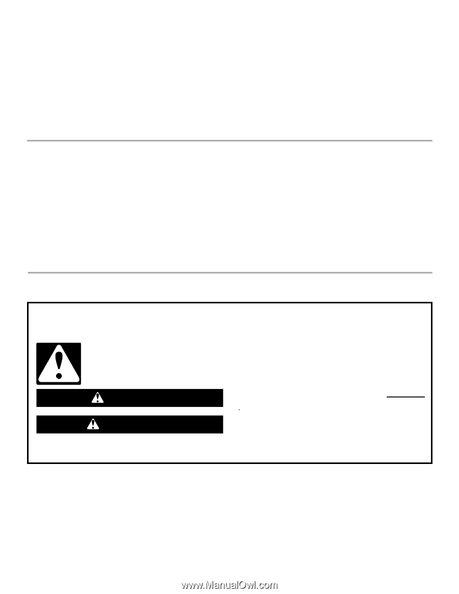
You can be killed or seriously injured if you don't immediately
You
can be killed or seriously injured if you don't follow
All safety messages will tell you what the potential hazard is, tell you how to reduce the chance of injury, and tell you what can
happen if the instructions are not followed.
Your safety and the safety of others are very important.
We have provided many important safety messages in this manual and on your appliance. Always read and obey all safety
messages.
This is the safety alert symbol.
This symbol alerts you to potential hazards that can kill or hurt you and others.
All safety messages will follow the safety alert symbol and either the word “DANGER” or “WARNING.”
These words mean:
follow instructions.
instructions.
DANGER
WARNING