Maytag MGDB800VU Installation Instructions
Maytag MGDB800VU - Bravos Steam Gas Dryer Manual
 |
View all Maytag MGDB800VU manuals
Add to My Manuals
Save this manual to your list of manuals |
Maytag MGDB800VU manual content summary:
- Maytag MGDB800VU | Installation Instructions - Page 1
13 COMPLETE INSTALLATION 13 Reverse Door Swing 14 TROUBLESHOOTING 15 Dryer Operation 15 Dryer Results 16 DRYER SAFETY Your safety and the safety of others are very important. We have provided many important safety messages in this manual and on your appliance. Always read and obey all safety - Maytag MGDB800VU | Installation Instructions - Page 2
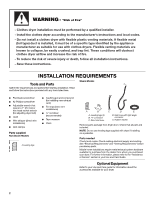
" before purchasing parts. Mobile home installations require metal exhaust system hardware available for purchase from the dealer from whom you purchased your dryer. For further information, please refer to the "Assistance or Service" section in your Use and Care Guide. Optional Equipment - Maytag MGDB800VU | Installation Instructions - Page 3
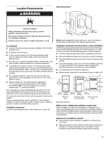
." ■ A sturdy floor to support total dryer weight of 200 lbs. (90.7 kg). Also consider combined weight of a companion appliance. ■ A level floor with maximum slope of 1" (25 mm) under entire dryer. If slope is greater than 1" (25 mm), install Extended Dryer Feet Kit, Part Number 279810. Clothes may - Maytag MGDB800VU | Installation Instructions - Page 4
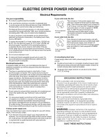
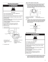
the serial/rating plate) on a separate 30-amp circuit, fused on both sides of the line. A time-delay fuse or circuit and follow the instructions provided for it here. ■ This dryer is manufactured ready supply connection must be used when the appliance is installed in a location where grounding - Maytag MGDB800VU | Installation Instructions - Page 5
through strain relief. Be sure that wire insulation on power supply cord is inside strain relief. Strain relief should have a tight fit with the dryer cabinet and be in a horizontal position. Do not further tighten strain relief screws at this point. E F A. Terminal block cover B. Hold-down screw - Maytag MGDB800VU | Installation Instructions - Page 6
screw. Tighten screw. 4. Now complete installation following instructions for your type of electrical connection: 4-wire (recommended 240-volt minimum, 30-amp, dryer power supply cord* 4-wire connection: Power supply cord 4-wire direct 5" (127 mm) A fused disconnect or circuit breaker box* - Maytag MGDB800VU | Installation Instructions - Page 7
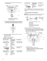
relief screws. 6. Insert tab of terminal block cover into slot of dryer rear panel. Secure cover with hold-down screw. 7. You have completed wire connections. Direct wire cable must have 5 ft. (1.52 m) of extra length so dryer can be moved if needed. Strip 5" (127 mm) of outer covering from end - Maytag MGDB800VU | Installation Instructions - Page 8
: Direct wire Use where local codes permit connecting cabinet-ground conductor to neutral wire. Direct wire cable must have 5 ft. (1.52 m) of extra length so dryer can be moved if needed. Strip 31/2" (89 mm) of outer covering from end of cable. Strip insulation back 1" (25 mm). If using 3-wire cable - Maytag MGDB800VU | Installation Instructions - Page 9
the other wires to outer terminal block screws. Tighten screws. 4. Tighten strain relief screw. 5. Insert tab of terminal block cover into slot of dryer rear panel. Secure cover with hold-down screw. 6. You have completed your electrical connection. Now go to "Venting Requirements." Optional 3-wire - Maytag MGDB800VU | Installation Instructions - Page 10
use a metal foil vent. Failure to follow these instructions can result in death or fire. Flexible metal vent metal vent must be fully extended and supported when the dryer is in its final location. ■ Service. For more information, see the "Assistance or Service" section in your Use and Care Guide. - Maytag MGDB800VU | Installation Instructions - Page 11
installations are shown. Refer to the manufacturer's instructions. A. Over-the-top installation (also available Service" section in your Use and Care Guide to order. ■ Over-the-Top Installation: Part Number 4396028 ■ Periscope Installation (For use with dryer vent to wall vent mismatch): Part - Maytag MGDB800VU | Installation Instructions - Page 12
remove the corner posts and cardboard. CONNECT INLET HOSE (STEAM MODELS) The dryer must be connected to the cold water faucet using the new inlet hoses faucet off and remove washer inlet hose. 2. Remove old rubber washer from inlet hose and replace with new rubber washer provided. If space permits - Maytag MGDB800VU | Installation Instructions - Page 13
on the dryer. 7. Wipe the dryer drum interior thoroughly with a damp cloth to remove any dust. 8. Read "Dryer Use" in your Use and Care Guide. 9. For of scale through the water system in the dryer. Over time, the buildup of lime scale may clog different parts of the water system, which will reduce - Maytag MGDB800VU | Installation Instructions - Page 14
an L2 code, there may be a problem with your home power supply keeping the dryer's heater from turning on. See "Troubleshooting." If you receive an AF code, your dryer vent may be crushed or blocked. See "Troubleshooting." NOTE: You may notice an odor when the dryer is first heated. This odor is - Maytag MGDB800VU | Installation Instructions - Page 15
1/4" (5 mm) of screw exposed. 7. Close door to engage door strike. TROUBLESHOOTING First try the solutions suggested here and possibly avoid the cost of a service call... Dryer Operation Dryer will not run ■ Has a household fuse blown, or has a circuit breaker tripped? There may be 2 household - Maytag MGDB800VU | Installation Instructions - Page 16
cleaned. ■ "E" Variable (E1, E2, E3) service codes: Call for service. Dryer Results Clothes are not drying satisfactorily, drying times are dryer requires a minimum of 1" (25 mm) of airspace, and, for most installations, the rear of the dryer requires 5" (127 mm). See the Installation Instructions.
-
 1
1 -
 2
2 -
 3
3 -
 4
4 -
 5
5 -
 6
6 -
 7
7 -
8
-
9
-
10
-
11
-
12
-
13
-
14
-
15
-
16
 |
 |
ELECTRIC DRYER INSTALLATION INSTRUCTIONS
U.S.A. ONLY
Para una version de estas instrucciones en español, visite www.Whirlpool.com
TABLE OF CONTENTS
TABLE OF CONTENTS
..................................................................
1
DRYER SAFETY
..............................................................................
1
INSTALLATION REQUIREMENTS
................................................
2
Tools and Parts
............................................................................
2
Optional Equipment
.....................................................................
2
Location Requirements
................................................................
3
ELECTRIC DRYER POWER HOOKUP
.........................................
4
Electrical Requirements
...............................................................
4
Electrical Connection
...................................................................
5
VENTING
........................................................................................
10
Venting Requirements
................................................................
10
Plan Vent System
.......................................................................
11
Install Vent System
.....................................................................
12
INSTALL LEVELING LEGS
...........................................................
12
CONNECT VENT
...........................................................................
12
CONNECT INLET HOSE (STEAM MODELS)
..............................
13
LEVEL DRYER
..............................................................................
13
COMPLETE INSTALLATION
.......................................................
13
Reverse Door Swing
...................................................................
14
TROUBLESHOOTING
.................................................................
15
Dryer Operation
..........................................................................
15
Dryer Results
..............................................................................
16
W10267633A
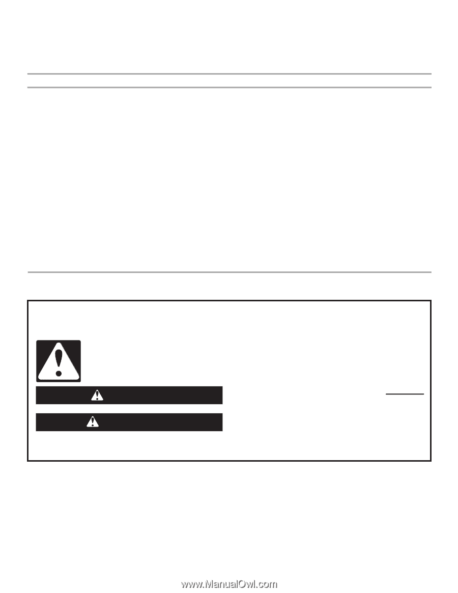
DRYER SAFETY
You
You can be kille
d
or seriously injure
d
if you
d
on't imme
d
iately
can be kille
d
or seriously injure
d
if you
d
on't follow
All
s
afety me
ss
age
s
will tell you what the potential hazard i
s
, tell you how to reduce the chance of injury, and tell you what can
happen if the in
s
truction
s
are not followed.
Your safety an
d
the safety of others are very important.
We have provided many important
s
afety me
ss
age
s
in thi
s
manual and on your appliance. Alway
s
read and obey all
s
afety
me
ss
age
s
.
Thi
s
i
s
the
s
afety alert
s
ymbol.
Thi
s
s
ymbol alert
s
you to potential hazard
s
that can kill or hurt you and other
s
.
All
s
afety me
ss
age
s
will follow the
s
afety alert
s
ymbol and either the word “DANGER” or “WARNING.”
The
s
e word
s
mean:
follow instructions.
instructions.
DANGER
WARNING