Maytag MGR7775 Installation Instructions
Maytag MGR7775 - 30 in. Ing Gas Range Manual
 |
UPC - 883049187068
View all Maytag MGR7775 manuals
Add to My Manuals
Save this manual to your list of manuals |
Maytag MGR7775 manual content summary:
- Maytag MGR7775 | Installation Instructions - Page 1
INSTALLATIONINSTRUCTIONS 30" (76.2 CM) FREESTANDINGGAS RANGES Table of Contents RANGE SAFETY 2 INSTALLATION REQUIREMENTS 4 Tools and Parts 4 Location Requirements 4 Electrical Requirements 6 Gas Supply Requirements 6 INSTALLATION INSTRUCTIONS 8 Unpack Range 8 Install Anti-Tip Bracket 8 Make - Maytag MGR7775 | Installation Instructions - Page 2
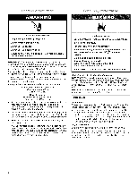
you what can happen if the instructions are not followed. Tip Over Hazard A child or adult can tip the range and be killed. Connect anti=tip bracket to rear range foot. Reconnect the anti=tip bracket, if the range is moved. Failure to follow these instructions can result in death or serious burns - Maytag MGR7775 | Installation Instructions - Page 3
WARNING: If the information in this manual is not followed exactly, a fire or explosion may result the gas supplier's instructions. • If you cannot reach your gas supplier, call the fire department. - Installation and service must be performed by a qualified installer, service agency or the gas - Maytag MGR7775 | Installation Instructions - Page 4
- Additional Installation Requirements The installation of this range must conform to the Manufactured Home Construction and Safety Standard, Title 24 CFR, Part 3280 (formerly the Federal Standard for Mobile Home Construction and Safety, Title 24, HUD Part 280). When such standard is not applicable - Maytag MGR7775 | Installation Instructions - Page 5
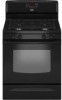
extend beyond cabinet fronts by 1/2"(13.0 mm) minimum. IMPORTANT: If installing a range hood or microwave hood combination above the range, follow the range hood or microwave hood combination installation instructions for dimensional clearances above the cooktop surface. B C A. 27_%_ '' (69.9 cm - Maytag MGR7775 | Installation Instructions - Page 6
service personnel instructions. Type of Gas Natural gas: This range is design-certified by CSA International for use with Natural gas or, after proper conversion, for use with LP gas. • This range is factory set for use with Natural gas. See "Gas Conversions" section. The model/serial rating - Maytag MGR7775 | Installation Instructions - Page 7
shown on the model/serial rating plate. Line pressure testing above 1/2psi gauge (14" WCP) The range and its individual shutoff valve gauge (14" WCP) or lower The range must be isolated from the gas supply piping system by closing its individual manual shutoff valve during any pressure testing of - Maytag MGR7775 | Installation Instructions - Page 8
-half turn. AB Tip Over Hazard A child or adult can tip the range and be killed. Connect anti=tip bracket to rear range foot. Reconnect the anti=tip bracket, if the range is moved. Failure to follow these instructions can result in death or serious burns to children and adults. Contact a qualified - Maytag MGR7775 | Installation Instructions - Page 9
home, you must secure the range to the floor. Any method of securing the range is adequate as long as it conforms to the standards in the "Location Requirements" section. 10. Continue installing your range using the following installation instructions service pipe G F. Manual gas shutoff valve - Maytag MGR7775 | Installation Instructions - Page 10
manual these instructions can white wheels in drawer guides range. A. Closed valve B. Open valve 3= Test all connections by brushing on an approved noncorrosive leak-detection solution. If bubbles appear, a leak is indicated. Correct any leak found. 4. Remove cooktop burner caps and grates from parts - Maytag MGR7775 | Installation Instructions - Page 11
Turn cooktop control knob to the "OFF" position. • Check that the range is plugged in. Check that the circuit breaker has not tripped or the , turn the control knobs to "Off" and contact your dealer or authorized service company for assistance. A. Control knob stem B. Screwdriver 1. Light 1 burner - Maytag MGR7775 | Installation Instructions - Page 12
to be adjusted, locate the air shutter near the center rear of the range. Loosen the locking screw and rotate the air shutter until the proper flame appears to light the bake and broil burners. Refer to the Use and Care Guide for proper operation of the oven controls. A. Air shutter B. Locking - Maytag MGR7775 | Installation Instructions - Page 13
and Care Guide for specific instruction on range operation. If range does not operate, check the following: • Household fuse is intact and tight, or circuit breaker has not tripped. • Range is plugged into a grounded 3 prong outlet. • Electrical supply is connected. • See "Troubleshooting" in the - Maytag MGR7775 | Installation Instructions - Page 14
and authorized service personnel. range is moved. Failure to follow these instructions can result in death or serious burns to children and adults. 1. Turn the manual shutoff valve to the closed position. 2. Unplug range or disconnect power. .......B A_J ........C A. To range B. Manual - Maytag MGR7775 | Installation Instructions - Page 15
Burner Rating Color Size ID Number 14,000 BTU 11,000 BTU 8,000 BTU 5,000 BTU Yellow/Orange Yellow/Brown Yellow/Black Yellow/White 1.07 electrode 4= Remove the cardboard orifice spud holder located on the back of the range near the gas inlet. Gas orifice spuds are stamped with a number, marked - Maytag MGR7775 | Installation Instructions - Page 16
have a slightly yellow tip. 3. Refer to "Complete Installation" in the "Installation Instructions" section of this manual to complete this procedure. Tip Over Hazard A child or adult can tip the range and be killed. Connect anti=tip bracket to rear range foot. Reconnect the anti=tip bracket, if the - Maytag MGR7775 | Installation Instructions - Page 17
one of the screws through the range cooktop to hold the orifice spud Natural Gas Orifice Spud Chart Burner Rating Color Size ID Number 17,000 Orange Red/Blue Red/Yellow Red/Brown Red/White Red/Brass 2.10 mm 2.00 mm Place LP gas orifice spuds in plastic parts bag for future use and keep with - Maytag MGR7775 | Installation Instructions - Page 18
1. Refer to the "Make Gas Connection" section for properly connecting the range to the gas supply. 2. Refer to the "Electronic Ignition System" section to "Complete Installation" in the "Installation Instructions" section of this manual to complete this procedure. A. Lock screw B. Orifice hood 18 - Maytag MGR7775 | Installation Instructions - Page 19
ANTI-TIPBRACKETTEMPLATE Cut on dotted lines and place the left edge against the left side cabinet and the top edge against the rear wall. Top edge Use this template to anchor the left rear leg of range. 19 - Maytag MGR7775 | Installation Instructions - Page 20
W10196161B © 2008. All rights reserved. 8/08 Printed in U.S.A.
-
 1
1 -
 2
2 -
 3
3 -
 4
4 -
 5
5 -
 6
6 -
 7
7 -
8
-
9
-
10
-
11
-
12
-
13
-
14
-
15
-
16
-
17
-
18
-
19
-
20
 |
 |

INSTALLATIONINSTRUCTIONS
30"(76.2 CM) FREESTANDINGGAS RANGES
Table of Contents
RANGE SAFETY
.............................................................................
2
INSTALLATION
REQUIREMENTS
................................................
4
Tools
and
Parts
............................................................................
4
Location Requirements
................................................................
4
Electrical
Requirements
...............................................................
6
Gas
Supply
Requirements
...........................................................
6
INSTALLATION
INSTRUCTIONS
..................................................
8
Unpack Range
.............................................................................
8
InstallAnti-Tip
Bracket
.................................................................
8
Make Gas Connection
.................................................................
9
Verify Anti-Tip Bracket
Location
................................................
10
Level Range
................................................................................
11
Electronic
Ignition System
.........................................................
11
Replace Oven Racks and Storage or Warming
Drawer
............
13
Complete
Installation
.................................................................
13
GAS CONVERSIONS
....................................................................
14
LP Gas Conversion
....................................................................
14
Natural Gas Conversion
.............................................................
16
ANTI-TIP
BRACKET
TEMPLATE
...............................................
19
iMPORTANT:
Installer:
Leave installation
instructions
with the homeowner.
Homeowner:
Keep installation
instructions
for future reference.
W10196161B