Maytag MMV1153WW Installation Instructions
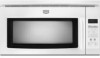
Maytag MMV1153WW - 1.5 cu. Ft. Microwave-Range Hood Combination Manual
 |
UPC - 719881170442
View all Maytag MMV1153WW manuals
Add to My Manuals
Save this manual to your list of manuals |
Maytag MMV1153WW manual content summary:
- Maytag MMV1153WW | Installation Instructions - Page 1
for further notes. These installation instructions cover different models. The appearance of your particular model may differ slightly from the illustration in these installation instructions. Table of Contents MICROWAVE HOOD COMBINATION SAFETY I INSTALLATION REQUIREMENTS 2. Tools and Parts - Maytag MMV1153WW | Installation Instructions - Page 2
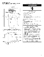
within cabinet opening. Support for weight of 150 Ibs (68 kg), which includes microwave oven and items placed inside the microwave oven and upper cabinet. Grounded electrical outlet inside upper cabinet. See "Electrical Requirements" section. NOTES: • If installing the microwave oven near a left - Maytag MMV1153WW | Installation Instructions - Page 3
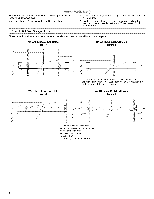
*30" (76.2 cm) is typical for 66" (167.6 cm) installation height. Exact dimensions may vary depending on type of range/cooktop below. T 17¼" (43.8 crn] T 16¼" _,1.3 cm) GROUNDING iNSTRUCTiONS [] For all cord connected appliances: The microwave oven must be grounded. In the event of an electrical - Maytag MMV1153WW | Installation Instructions - Page 4
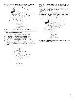
together and set aside. 3. Remove 2 screws attaching blower motor to back of microwave oven. .... t{ A. Screws (in recessed holes) 4, Lift blower motor out of microwave oven. The microwave oven is set for recirculation installation. For wall or roof venting, changes must be made to the venting - Maytag MMV1153WW | Installation Instructions - Page 5
motor is not positioned with flat sides facing the back of the microwave oven (as shown), performance will be poor. 6. Reattach blower motor to back of microwave oven with 2 screws removed in Step 3 of "Wall Venting Installation Only." Securely tighten screws. NOTE: If blower motor is not correctly - Maytag MMV1153WW | Installation Instructions - Page 6
studs exist within the cabinet opening, do not install the microwave oven. See illustrations in "Possible Wall Stud holes (on mounting plate) B. Cabinet opening vertical centerline C. Waft stud centerlines D. Holes for lag screws E. Support tabs F. Mounting plate center markers // , i c I 6 - Maytag MMV1153WW | Installation Instructions - Page 7
The microwave oven must be installed on a minimum of 1 wall stud, preferably 2, using a minimum of 1 lag screw, preferably 2. 1. Using measuring tape, find and clearly mark the vertical centerline of the opening. A .....}.L..j._.._..o........_. 5. With the support tabs facing forward (see - Maytag MMV1153WW | Installation Instructions - Page 8
support tabs of the mounting plate facing forward, insert a 1/4-20 x 3" round-head bolt through the end hole that fits over the 3/4" (19 mm) hole drilled in Step 3 of "Installation holes in the top of the microwave oven. NOTE: If the upper use as guides. 4. Make sure the 10" (25.4 - Maytag MMV1153WW | Installation Instructions - Page 9
1/4-20 x 3" bolts and washers used to secure the microwave oven to the upper cabinet. For Roof Venting Installation Only 7. Cut 3/4" (19 mm) hole at one corner 2 sheet metal screws. A. Mounting plate B. Support tabs 4= With front of microwave oven still tilted, thread power supply cord through the - Maytag MMV1153WW | Installation Instructions - Page 10
the vent fan. 5. If the microwave oven does not operate: • problem continues, call an electrician. • Check that the power supply cord is plugged into a grounded 3 prong outlet. • See the User Instructions for troubleshooting information. Installation is now complete. Save Installation Instructions - Maytag MMV1153WW | Installation Instructions - Page 11
DESIGN SPECIFICATIONS This section is intended for architectural designer and builder/contractor reference only. NOTES: • Vent materials needed for installation are not provided with microwave hood. We do not recommend using a flexible metal vent. To avoid possible product damage, be sure to vent - Maytag MMV1153WW | Installation Instructions - Page 12
vent between the damper assembly and rectangular to round transition piece must be installed to keep the damper from sticking. ASSISTANCE Call your authorized dealer or service center. When you call, you will need the microwave oven model number and serial number. Both numbers can be found on the
-
 1
1 -
 2
2 -
 3
3 -
 4
4 -
 5
5 -
 6
6 -
 7
7 -
8
-
9
-
10
-
11
-
12
 |
 |
MICROWAVE HOOD COMBINATION
INSTALLATIONINSTRUCTIONS
This product
is suitable for use above electric or gas cooking
products
up to and including
36" (91.4 cm) wide. See "Installation
Requirements"
section for further
notes.
These installation
instructions
cover different
models.
The appearance
of your particular
model
may differ slightly from the illustration
in
these installation
instructions.
Table of
Contents
MICROWAVE HOOD COMBINATION
SAFETY
..............................
I
INSTALLATION
REQUIREMENTS
...................................................
2
Tools and Parts
...............................................................................
2
Remove Cardboard Template
........................................................
2
Location Requirements
...................................................................
2
Product Dimensions
.......................................................................
3
Electrical Requirements
..................................................................
3
INSTALLATION INSTRUCTIONS
.....................................................
4
Remove Mounting Plate
.................................................................
4
Rotate Blower Motor
.......................................................................
4
Locate Wall Stud(s)
.........................................................................
6
Mark RearWall
................................................................................
7
Drill Holes in RearWall
....................................................................
7
Attach Mounting Plate to Wall
........................................................
8
Prepare Upper Cabinet
...................................................................
8
Install DamperAssembly
................................................................
9
Install the Microwave Oven
............................................................
9
Complete Installation
....................................................................
10
VENTING DESIGN SPECIFICATIONS
............................................
11
ASSISTANCE
...................................................................................
12
Replacement Parts
.......................................................................
12
Accessories
...................................................................................
12
MICROWAVE HOOD COMBINATION
SAFETY
Your
safety
and
the safety
of others
are very
important.
We have provided
many important
safety messages
in this manual and on your appliance.
Always read and obey all safety
messages.
This is the safety alert symbol.
This symbol
alerts you to potential
hazards that can kill or hurt you and others.
All safety
messages
will follow the safety alert symbol and either the word "DANGER"
or "WARNING."
These words mean:
You can be killed or seriously
injured if you don't immediately
follow
instructions.
You can be killed or seriously
injured
if you don't
follow
instructions.
All safety messages
will tell you what the potential
hazard is, tell you how to reduce the chance
of injury, and tell you what can
happen
if the instructions
are not followed.
W10238252A