Maytag MMV5208WS Installation Instructions
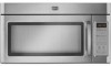
Maytag MMV5208WS - 2.0 cu. Ft. Combination Range Hood-Microwave Manual
 |
UPC - 883049158419
View all Maytag MMV5208WS manuals
Add to My Manuals
Save this manual to your list of manuals |
Maytag MMV5208WS manual content summary:
- Maytag MMV5208WS | Installation Instructions - Page 1
Holes in Rear Wall 7 Attach Mounting Plate to Wall 8 Prepare Upper Cabinet 8 Install Damper Assembly 9 Install the Microwave Oven 9 Complete Installation 10 VENTING DESIGN SPECIFICATIONS 11 ASSISTANCE 12 Replacement Parts 12 Accessories 12 MICROWAVE HOOD COMBINATION SAFETY Your safety - Maytag MMV5208WS | Installation Instructions - Page 2
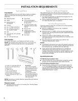
(for wall or roof venting) Not Shown: Upper cabinet template Mounting plate (attached to back of microwave oven) Cardboard template (part of packaging) Aluminum grease filters Charcoal filters (Depending on model, charcoal filters may not be included. See User Instructions.) NOTE: Depending on - Maytag MMV5208WS | Installation Instructions - Page 3
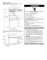
for 66" (167.6 cm) installation height. Exact dimensions may vary depending on type of range/cooktop below. Product Dimensions 17¹⁄₄" (43.8 cm) 16¹⁄₄" (41.3 cm) (411.06¹c⁄₈m") 29⁷⁄₈" (76.0 cm) GROUNDING INSTRUCTIONS ■ For all cord connected appliances: The microwave oven must be grounded. In - Maytag MMV5208WS | Installation Instructions - Page 4
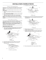
INSTALLATION INSTRUCTIONS Remove Mounting Plate Depending on your model, the mounting plate may be in the foam packaging, or it may be attached to the back of the microwave oven. NOTE: To avoid possible damage to the work surface, cover the work surface. 1. Remove any remaining contents from the - Maytag MMV5208WS | Installation Instructions - Page 5
back of microwave oven with 2 screws removed in Step 3 of "Wall Venting Installation Only." Securely tighten screws. NOTE: If blower motor is not correctly oriented, the 2 screws removed in Step 3 cannot be reattached to the microwave oven. 7. Reattach damper plate. Make sure damper plate tabs are - Maytag MMV5208WS | Installation Instructions - Page 6
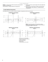
venting installation can be done. Wall Stud at One End Hole Figure 3 Wall Studs at Both End Holes Figure 4 B D B A A,D A,D A,D E E E E C C C C F F A. End holes (on mounting plate) B. Cabinet opening vertical centerline C. Wall stud centerlines D. Holes for lag screws E. Support - Maytag MMV5208WS | Installation Instructions - Page 7
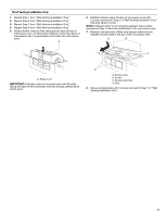
microwave oven must be installed and mark the wall with the dimensions described in Step 4. D A support tabs facing forward (see illustrations in "Locate Wall Stud(s)" section), align the mounting plate locations. 7. Set the mounting plate aside. Wall Venting Installation Only Upper cabinet bottom - Maytag MMV5208WS | Installation Instructions - Page 8
wall behind the microwave oven (as installed) has a partial wall covering (for example, tile backsplash), be sure the "Rear Wall" arrows align to the thickest part of the rear wall (for example, the thickness of the tiles rather than the drywall). 4. Make sure the 10" (25.4 cm) dimension from the - Maytag MMV5208WS | Installation Instructions - Page 9
with 2 sheet metal screws. A B A. Mounting plate B. Support tabs 4. With front of microwave oven still tilted, thread power supply cord through the power supply cord hole in the bottom of the upper cabinet. 5. Rotate microwave oven up toward upper cabinet. NOTE: If venting through the wall, make - Maytag MMV5208WS | Installation Instructions - Page 10
cabinet bottom and the microwave oven. A 2. Connect vent to damper assembly. A B A. Vent B. Damper assembly (under vent) Complete Installation 1. Install filters. Refer to the User Instructions for filter placement. WARNING A. Bolts For Roof Venting Installation Only 1. Insert damper assembly - Maytag MMV5208WS | Installation Instructions - Page 11
VENTING DESIGN SPECIFICATIONS This section is intended for architectural designer and builder/contractor reference only. NOTES: ■ Vent materials needed for installation are not provided with microwave hood combination. ■ We do not recommend using a flexible metal vent of the microwave oven and the - Maytag MMV5208WS | Installation Instructions - Page 12
installation hardware needs to be replaced, call us at our toll free number listed in the User Instructions. Following is a list of available replacement parts. You will need your model number located on the front facing of the microwave oven opening, behind the door. ■ Damper Assembly ■ Mounting
-
 1
1 -
 2
2 -
 3
3 -
 4
4 -
 5
5 -
 6
6 -
 7
7 -
8
-
9
-
10
-
11
-
12
 |
 |
MICROWAVE HOOD COMBINATION
INSTALLATION INSTRUCTIONS
MICROWAVE HOOD COMBINATION SAFETY
This product is suitable for use above electric or gas cooking products up to and including 36" (91.4 cm) wide. See “Installation
Requirements” section for further notes.
These installation instructions cover different models. The appearance of your particular model may differ slightly from the illustration in
these installation instructions.
Table of Contents
MICROWAVE HOOD COMBINATION SAFETY
..............................
1
INSTALLATION REQUIREMENTS
...................................................
2
Tools and Parts
...............................................................................
2
Remove Cardboard Template
........................................................
2
Location Requirements
...................................................................
2
Product Dimensions
.......................................................................
3
Electrical Requirements
..................................................................
3
INSTALLATION INSTRUCTIONS
.....................................................
4
Remove Mounting Plate
.................................................................
4
Rotate Blower Motor
.......................................................................
4
Locate Wall Stud(s)
.........................................................................
6
Mark Rear Wall
................................................................................
7
Drill Holes in Rear Wall
....................................................................
7
Attach Mounting Plate to Wall
........................................................
8
Prepare Upper Cabinet
...................................................................
8
Install Damper Assembly
................................................................
9
Install the Microwave Oven
............................................................
9
Complete Installation
....................................................................
10
VENTING DESIGN SPECIFICATIONS
............................................
11
ASSISTANCE
...................................................................................
12
Replacement Parts
.......................................................................
12
Accessories
...................................................................................
12
W10344702B
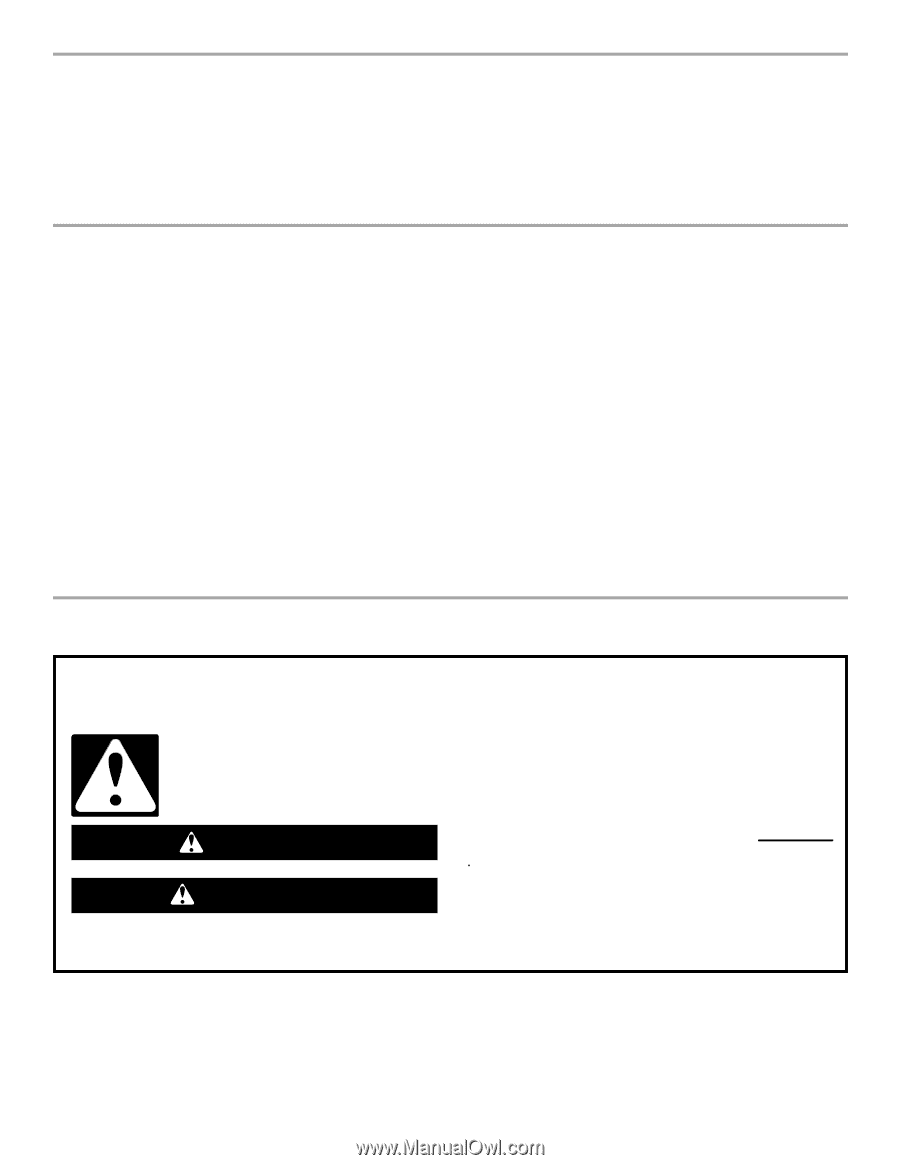
You can be killed or seriously injured if you don't immediately
You
can be killed or seriously injured if you don't follow
All safety messages will tell you what the potential hazard is, tell you how to reduce the chance of injury, and tell you what can
happen if the instructions are not followed.
Your safety and the safety of others are very important.
We have provided many important safety messages in this manual and on your appliance. Always read and obey all safety
messages.
This is the safety alert symbol.
This symbol alerts you to potential hazards that can kill or hurt you and others.
All safety messages will follow the safety alert symbol and either the word “DANGER” or “WARNING.”
These words mean:
follow instructions.
instructions.
DANGER
WARNING