Motorola SB6121 Installation Guide - Page 14
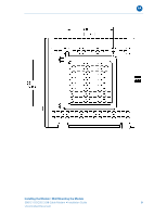
Wall Mounting Template, the electrical outlet.
 |
View all Motorola SB6121 manuals
Add to My Manuals
Save this manual to your list of manuals |
Page 14 highlights
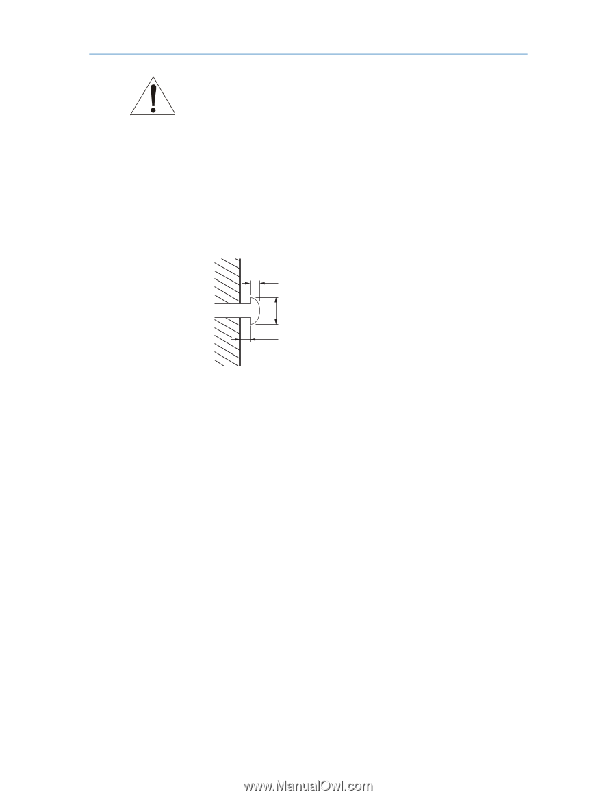
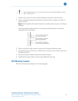
B Before drilling holes in the wall, check the structure for potential damage to water, gas, or electrical lines. 1. Position and secure the wall mounting template on the wall to mark the holes. 2. Select an appropriate depth and diameter to drill the holes to a depth of at least 1½ inches (3.8 cm). Note: The hole depth will be determined by the installer and by the type of hardware selected. See the dimension diagram below for the spacing needed between the wall and underside of the screw head: 2.6 mm (0.10") maximum screw head thickness 9.0 mm (0.35") maximum screw head diameter 2.5 mm (0.10") minimum screw head to wall spacing 3. After mounting the cable modem, reconnect the coaxial and Ethernet cable. 4. Re-plug the power cord into the +12VDC Power connector on the cable modem and the electrical outlet. 5. Properly arrange the cables to prevent any safety hazards. 6. Verify that the cable modem is still securely attached to the wall. Wall Mounting Template Print the wall mounting template on the following page. Installing the Modem • Wall Mounting the Modem SB6121 DOCSIS 3.0® Cable Modem • Installation Guide 8 Uncontrolled Document
-
 1
1 -
2
-
3
-
4
-
5
-
6
-
7
-
8
-
 9
9 -
 10
10 -
 11
11 -
 12
12 -
 13
13 -
 14
14 -
 15
15 -
 16
16 -
 17
17 -
 18
18 -
 19
19 -
20
-
21
-
22
-
23
-
24
-
25
-
26
-
27
 |
 |