NEC MM2000 MM2000B : MM2000B User Manual
NEC MM2000 Manual
 |
View all NEC MM2000 manuals
Add to My Manuals
Save this manual to your list of manuals |
NEC MM2000 manual content summary:
- NEC MM2000 | MM2000B : MM2000B User Manual - Page 1
Multimedia Switcher for DLP Cinema® Projector MM2000 User's Manual NEC Viewtechnology, Ltd. - NEC MM2000 | MM2000B : MM2000B User Manual - Page 2
USER-SERVICEABLE PARTS INSIDE. REFER SERVICING TO QUALIFIED SERVICE information should be read carefully to avoid problems. WARNING TO PREVENT FIRE OR SHOCK accordance with the installation manual, may cause harmful . Important Safeguards These safety instructions are to ensure the long life - NEC MM2000 | MM2000B : MM2000B User Manual - Page 3
object removed by a qualified service personnel. • Do not support branches for questions relating to unclear points, malfunctions and repairs of the product. In Europe NEC electronic products carrying the mark (left) must be disposed of separately from normal household waste. This includes projectors - NEC MM2000 | MM2000B : MM2000B User Manual - Page 4
de sociétés mentionnés dans ce mode d'emploi peuvent être des marques commerciales de leur propriétaire respectif. Mesures de sécurité importantes Ces instructions de sécurité garantissent la longévité de votre commutateur et préviennent les risques d'incendie et de décharge électrique. Lisez-les et - NEC MM2000 | MM2000B : MM2000B User Manual - Page 5
Technical Centre Adresse : Unit G, Stafford Park 12, Telford TF3 3BJ, U.K. Téléphone : +44 1952 237000 Fax : +44 1952 237006 En Amérique du Nord NEC Corporation of America Division Cinéma Numérique Adresse : 4111 West Alameda Avenue Suite 412 Burbank, CA 91505 Téléphone : 818 557 2500 *Si la ligne - NEC MM2000 | MM2000B : MM2000B User Manual - Page 6
Important Information Wichtige Informationen Vorsichtsmaßnahmen Lesen Sie sich dieses Handbuch bitte sorgfältig durch, bevor Sie den MM2000 Switcher benutzen, und bewahren Sie das Handbuch in greifbarer Nähe als spätere Referenz auf. Die Seriennummer Ihres Gerätes finden Sie auf der Unterseite des - NEC MM2000 | MM2000B : MM2000B User Manual - Page 7
/ European Technical Centre Addresse: Unit G, Stafford Park 12, Telford TF3 3BJ, U.K. Telefon: +44 1952 237000 Fax-Nummer: +44 1952 237006 In Nordamerika NEC Corporation of America Digital-Cinema-Abteilung Adresse: 4111 West Alameda Avenue Suite 412 Burbank, CA 91505 Telefon: 818 557 2500 *Falls die - NEC MM2000 | MM2000B : MM2000B User Manual - Page 8
Important Information (MEMO) G-3 - NEC MM2000 | MM2000B : MM2000B User Manual - Page 9
...4 2.Installation 10 2-1. Making Connections ...10 2-2. Connecting Your Projector ...11 2-3. Connecting to the Image Input Terminals ...12 2-4. 5.Maintenance 20 5-1. Cleaning the Cabinet ...20 6.Appendix 21 6-1. Troubleshooting ...21 6-2. Error code list ...22 6-3. Compatible input signal - NEC MM2000 | MM2000B : MM2000B User Manual - Page 10
1-1. Features • 3D Motion Adaptive I/P Conversion Supports a Multi-directional Filter for HDTV Differing from SDI interface slot, there is complete 10-bit processing up to the interface unit of the projector. This makes it possible to attain images with high-bit depth. • Per-pixel Motion Adaptive - NEC MM2000 | MM2000B : MM2000B User Manual - Page 11
contents are as follows: • Multimedia Switcher (MM2000) 1. Introduction • Ferrite clamp core (for Power cable / RGB cables) x2 • Band x2 • User's Manual User's Manual (For Japan) • Power cable x3 • Power cable for Japan (AC100V) • Power cable for North America (AC120V) • Power cable for Europe - NEC MM2000 | MM2000B : MM2000B User Manual - Page 12
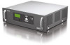
1. Introduction 1-3. Getting to Know Your Switcher 1-3-1. Front of the Switcher Control panel (See page 5) Ventilation (inlet) 1-3-2. Rear of the Switcher Ventilation (outlet) Control terminals / Image output terminals (See page 6) Handles Main power switch (See page 16) AC INPUT (See page 15) - NEC MM2000 | MM2000B : MM2000B User Manual - Page 13
condition while you are in the adjustment or setting menu. 10. Reset Switch Don't touch this switch except for the service personnel. If a person except for the service personnel touched this switch, the Switcher breaks down, and contents of a setup inside the Switcher are erased. 6. POWER Button - NEC MM2000 | MM2000B : MM2000B User Manual - Page 14
LAN card. 4. USB port (type A) This terminal is for the service personnel. It is used for maintenance of the switcher. 5. Main power switch Connect this terminal with the DVI-A input terminal on the NC series projector. Use a commercially available DVI-D signal cable (single link). 8. DVI - NEC MM2000 | MM2000B : MM2000B User Manual - Page 15
1. Introduction 1-3-5. Image Input terminals You can mount various interface boards to any position you want among slots 1 to 4. For removal and installation of the interface board, see page 13. 1 3 2 1.SLOT 1 (MM-VIDEO) MM-VIDEO interface board is standard equipment. 4 2. SLOT 2 (MM-RGB) MM- - NEC MM2000 | MM2000B : MM2000B User Manual - Page 16
1. Introduction 1-3-6. Option Boards MM-SDI Interface Board (Option) The SDI signal input board is available as an option. (1) (2) (3) (4) (1) STATUS Indicator Steady green light ....... Shows that a signal is present. Steady red light Shows that there is no signal or an error occurs. Steady - NEC MM2000 | MM2000B : MM2000B User Manual - Page 17
MM-DVI Interface Board (Option) The DVI signal input board is available as an option. 1. Introduction (1) (2) (1) DVI-D Input Connector (DVI-D 24 Pin) Use a DVI-D Signal cable and connect it to the DVI output connector of a computer. (2) ACT Indicator Steady green light ....... Shows that this - NEC MM2000 | MM2000B : MM2000B User Manual - Page 18
2. Installation 2-1. Making Connections NOTE When using with a notebook PC, be sure to connect between the Switcher and the notebook PC before turning on the power to the notebook PC. In most cases signal cannot be output from RGB output unless the notebook PC is turned on after connecting with - NEC MM2000 | MM2000B : MM2000B User Manual - Page 19
this unit using two commercially available DVI-D signal cables. Alternatively, when a mode to control this unit from the projector (linked mode) is used, connect this unit with the projector using a LAN cable. DVI OUT-B LAN DVI OUT-A LAN cross cable (not supplied) MM2000 DVI-D signal cable (not - NEC MM2000 | MM2000B : MM2000B User Manual - Page 20
2. Installation 2-3. Connecting to the Image Input Terminals This Switcher has two interface boards, MM-VIDEO and MM-RGB as standard equipment. See page 7. Connect required video signals. Four interface boards can be inserted in the Switcher at the same time. See page 13. COMPONENT MM2000 Ferrite - NEC MM2000 | MM2000B : MM2000B User Manual - Page 21
2. Installation 2-4. Install the Option Boards and Expand the Image Input Terminals Four types of option boards are available for the Switcher. Please purchase as required. Warning When installing or removing the board from the Switcher, do so after turning off the main power switch of the Switcher. - NEC MM2000 | MM2000B : MM2000B User Manual - Page 22
mode). Contact your dealer/distributor about use of the switcher in standalone mode. [Example of Connection with LAN] Touch panel controller (option) Server NC series projector Hub LAN cable* (not supplied) PC LAN PC MM2000 * When the switcher and PC are connected, use the LAN cross cable. 14 - NEC MM2000 | MM2000B : MM2000B User Manual - Page 23
2. Installation 2-6. Connecting the Supplied Power Cable Connect the supplied power cable to the Switcher. First connect the supplied power cable's three-pin plug to the AC IN of the Switcher, and then connect the other plug of the supplied power cable in the wall outlet. Make sure that the prongs - NEC MM2000 | MM2000B : MM2000B User Manual - Page 24
connected to this unit. Refer to the Projector User's Manual for details on how to operate the projector. The procedures to turn on and off : main power switch and POWER button. Turn on the power switch of the projector connected to the Switcher. To turn on the main power to the Switcher, press - NEC MM2000 | MM2000B : MM2000B User Manual - Page 25
3-2. Turning off the Switcher To turn off the Switcher: First press the POWER (ON/STAND BY) button on the Switcher cabinet for a minimum of 1 second. The POWER indicator will glow orange. Power on Standby POWER Steady green light ON/STAND BY POWER Steady orange light Second, turn off the - NEC MM2000 | MM2000B : MM2000B User Manual - Page 26
4. LCD Menu 4-1. Basic operation from LCD screen menu With the LCD screen menu, you can display various information about this unit. 4-1-1. Screen display When not displaying the menu, the following screen is usually displayed. When in standby When this unit is in the standby state, the following is - NEC MM2000 | MM2000B : MM2000B User Manual - Page 27
4-1-2. Operating menus Preparation: Turn on the unit (See page 16). 4. LCD Menu 1 Press the MENU button. A menu is displayed on the LCD screen. 2 Press the SELECT ̇̈ button to display "Version". As you press the SELECT ̇̈ button, the display changes among "Version" ←→ "IP Address" ←→ "Error Code - NEC MM2000 | MM2000B : MM2000B User Manual - Page 28
5. Maintenance 5-1. Cleaning the Cabinet 1 Turn off the Switcher before cleaning. 2 Clean the cabinet periodically with a damp cloth. If heavily soiled, use a mild detergent. Never use strong detergents or solvents such as alcohol or thinner. 20 - NEC MM2000 | MM2000B : MM2000B User Manual - Page 29
the trouble cannot be corrected, please contact your dealer/distributor for instructions or repair. 6-1-1. Common Problems & Solutions Problem Does current signal. For RGB (computer) input, is it a resolution and frequency supported by the input signals? Check the resolution of the PC. If the PC - NEC MM2000 | MM2000B : MM2000B User Manual - Page 30
F5 Fn + F7 Fn + F8 Fn + F10 NEC, Panasonic, Gateway, SOTEC HP TOSHIBA, SHARP, MITSUBISHI SONY laptop PC from a manufacturer not listed in the table, refer to your laptop's help menu or your owner's manual laptop. If the external output signal is greatly out of range of the signals that this projector - NEC MM2000 | MM2000B : MM2000B User Manual - Page 31
74.25 74.25 74.25 *1 Composite sync signal does not support. *2 Sync on Green signal does not support. • At the time of shipping, adjustment is made to the on the type of personal computer. • SDTV and HDTV signals also support a vertical frequency of fV/1.001. • Composite sync and other signals - NEC MM2000 | MM2000B : MM2000B User Manual - Page 32
105 kHz Vertical frequency: 24 Hz to 96 Hz 1 input, dual link supported Maximum pixel clock frequency: 220 MHz 2 input SDTV: SMPTE 259M Level-C BNC x 1 DVI-D x 2 (DVI OUT-A, DVI OUT-B) A Type x1 (For service personnel) RJ-45 x 1 D-Sub 9 pin x 1 (For service personnel) Input / Output Terminals 24 - NEC MM2000 | MM2000B : MM2000B User Manual - Page 33
Projector connection Operational Temperature Operational Humidity Storage Temperature Storage Humidity 6. Appendix Type II x 1 (For service MM-DVI • In the table above, specifications are when connected to the projector. • Note that the specifications and design can change without prior notice. • - NEC MM2000 | MM2000B : MM2000B User Manual - Page 34
ée composants) RCA (L/MONO, R) x 1 (pas de fonction DVI-D x 1 Entrée SDI Sortie SDI IN BNC x 2 BNC x 1 DVI-D x 2 (DVI OUT-A, DVI OUT-B) A Type x1 (Pour le personnel de service) RJ-45 x 1 D-Sub à 9 broches x 1 (Pour le personnel de - NEC MM2000 | MM2000B : MM2000B User Manual - Page 35
Température de fonctionnement Humidité de fonctionnement Température de stockage Humidité de stockage Type II x 1 (Pour le personnel de service) Commutation continue rapide (extension de fonction) Image par image, côte à côte (extension de fonction) Correction verticale (extension de fonction - NEC MM2000 | MM2000B : MM2000B User Manual - Page 36
6. Appendix Technische Daten Modellnummer Bildeingang Bildeingang (Technischen Daten der optionalen Karte) Bildausgang Bildsignalbearbeitung Eingangsschlitz MM-VIDEO (Standardboard) MM-RGB (Standardboard) MM-DVI (Optionales Board) MM-SDI (Optionales Board) Ausgangsanschluss USB-Port LAN-Port PC- - NEC MM2000 | MM2000B : MM2000B User Manual - Page 37
6. Appendix PC-Karte Funktion Umgebung Lagerungsumgebung Stromversorgung Maße Nettogewicht Angewandte Bildumschaltung 2-facher Bildschirm-Modus Trapezkorrektur Projektor-Anschluss Betriebstemperatur Luftfeuchtigkeit Lagertemperatur Luftfeuchtigkeit bei Lagerung Typ II x 1 (Für servicepersonal) - NEC MM2000 | MM2000B : MM2000B User Manual - Page 38
6. Appendix 6-5. Cabinet Dimensions Units = mm 30 - NEC MM2000 | MM2000B : MM2000B User Manual - Page 39
© NEC Viewtechnology, Ltd. 2006 Printed in Japan Ver.1 08/06 - NEC MM2000 | MM2000B : MM2000B User Manual - Page 40
Printed on recycled paper 7N8P6981 MM2000 User's Manual
-
 1
1 -
 2
2 -
 3
3 -
 4
4 -
 5
5 -
 6
6 -
 7
7 -
8
-
9
-
10
-
11
-
12
-
13
-
14
-
15
-
16
-
17
-
18
-
19
-
20
-
21
-
22
-
23
-
24
-
25
-
26
-
27
-
28
-
29
-
30
-
31
-
32
-
33
-
34
-
35
-
36
-
37
-
38
-
39
-
40
 |
 |

MM2000
User’s Manual
Multimedia Switcher for DLP Cinema
®
Projector
NEC Viewtechnology, Ltd.