NEC NP-V260X NP216 : NP01UCM (ceiling mount) instructions - Page 4
Caution
 |
UPC - 805736036596
View all NEC NP-V260X manuals
Add to My Manuals
Save this manual to your list of manuals |
Page 4 highlights
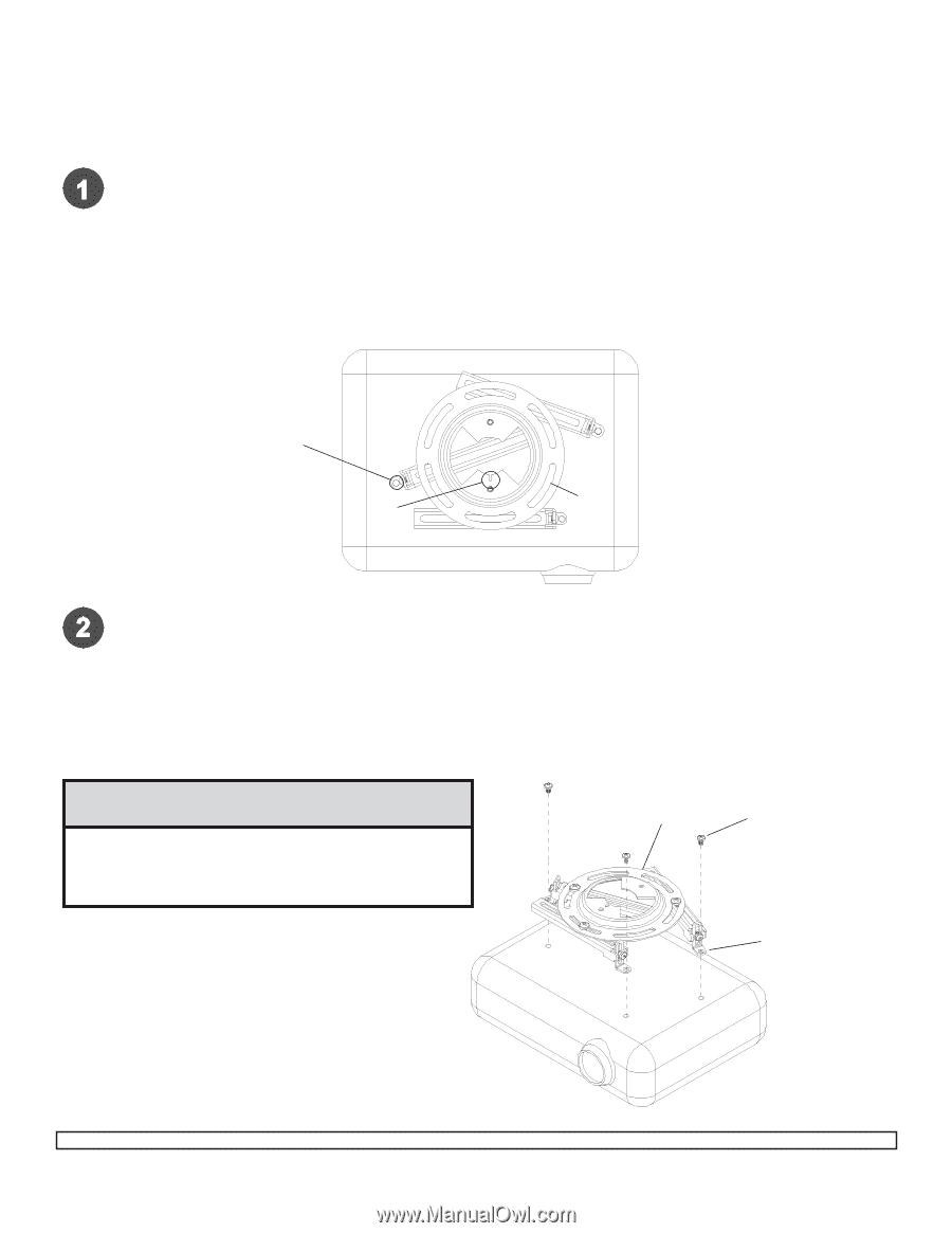
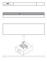
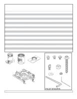
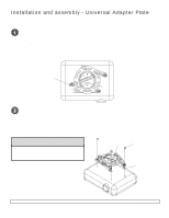
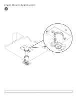
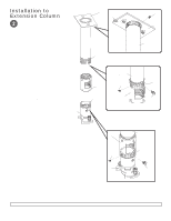
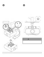
Installation and assembly - Universal Adapter Plate Note: The projector you are installing may differ in appearance from the sample illustrated below. Place projector upside down. Locate adapter plate (L) with notch facing forward as close to projector center of gravity as possible without covering any mounting holes. Loosen channels, and if there are only three mounting holes remove fourth channel. Using one channel for each mounting hole, position feet of channels over mounting holes as shown below. Important: If projector does not have at least three mounting holes, do not use this adapter plate. Note: Some projectors have feet which can be removed and the corresponding threaded insert can be used for a mounting hole. Note: Once channels are in position retighten fasteners. *Notch indicates front of projector. Mounting hole L * Generic Projector Attach adapter plate (L) to projector using one screw (M, N, O, or P) for each channel as shown below. Tighten all screws, while keeping the center of gravity. Be sure that adapter plate (L) is straight. Adjust the feet of the channels to keep the adapter plate level. Tighten all screws with 4 mm security allen wrench (B) or wrench provided with projector mount, while keeping the center of gravity. If M3 screws are used, tighten using 2 mm security allen wrench (Q). Note: Projectors will require different size screws for mounting. Use a combination of screws (M, N, O, or P) and foot adjustment that will result in channels of adapter plate (L) fitting tightly against projector. Important: In order to properly engage the threads in the mounting holes, the screw must be turned at least 3 full turns. Note: If using screw (M), place washer (R) between screw (M) and foot of channel. CAUTION L Generic Screw • It is the responsibility of the installer to ensure that the projector is properly ventilated. Feet of channels are used to raise the mount off the projector surface. Foot of Channel Visit the NEC Web Site at www.necsam.com 4 of 9 ISSUED: 04-11-06 SHEET #: 055-9458-1 For customer care call 1-800-729-0307 or 708-865-8870.
-
 1
1 -
 2
2 -
 3
3 -
 4
4 -
 5
5 -
 6
6 -
 7
7 -
 8
8 -
 9
9
 |
 |