NEC PX-61XM1A 61MP1 - Page 11
Rear View/ Terminal Board - power supply
 |
View all NEC PX-61XM1A manuals
Add to My Manuals
Save this manual to your list of manuals |
Page 11 highlights
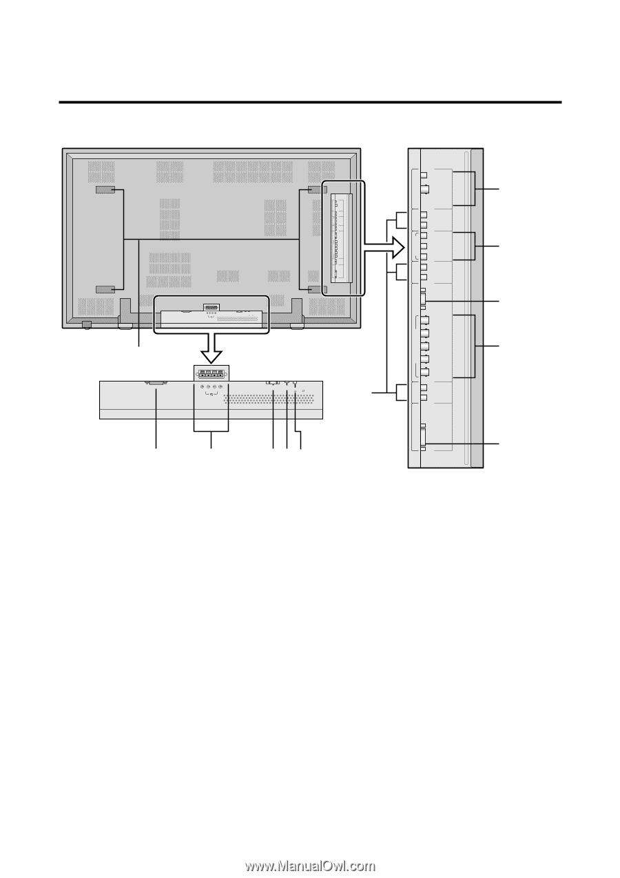
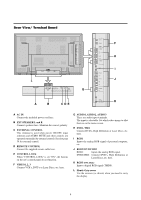
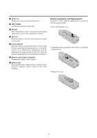
Rear View/ Terminal Board AUDIO 1 DVD1 / HD1 AUDIO 2 VIDEO 1 VIDEO 2 VIDEO 3 L(MONO) R Y CB/PB CR/PR L(MONO) R RGB 1 R/CR/PR G/Y B/CB/PB HD VD L(MONO) R RGB 3 (Digital RGB) RGB2 / DVD2/ HD2 AUDIO 3 AC IN RIGHT LEFT SPEAKERS MUST HAVE MORE THAN 7WATT RATING IMPEDANCE 6 OHM EXTERNAL CONTROL REMOTE CONTROL CONTROL LOCK ON / OFF L AC IN RIGHT LEFT SPEAKERS MUST HAVE MORE THAN 7WATT RATING IMPEDANCE 6 OHM EXTERNAL CONTROL REMOTE CONTROL CONTROL LOCK ON / OFF G A B CDE AUDIO 3 RGB2 / DVD2 / HD2 AUDIO 2 DVD1 /HD1 AUDIO 1 VIDEO 1 VIDEO 2 VIDEO 3 L(MONO) R Y CB/PB CR/PR L(MONO) R RGB 1 R/CR/PR G/Y B/CB/PB HD VD L(MONO) R RGB 3 (Digital RGB) F H I J K A AC IN Connect the included power cord here. B EXT SPEAKER L and R Connect speakers here. Maintain the correct polarity. C EXTERNAL CONTROL This terminal is used when power ON/OFF, input selection and AUDIO MUTE and other controls are operated externally (by external control). See also page 39 for external control. D REMOTE CONTROL Connect the supplied remote cable here. E CONTROL LOCK When "CONTROL LOCK" is set "ON", the buttons on the set's control panel do not function. F VIDEO1, 2, 3 Connect VCR's, DVD's or Laser Discs, etc. here. G AUDIO1, AUDIO2, AUDIO3 These are audio input terminals. The input is selectable. Set which video image to allot them to on the menu screen. H DVD1 / HD1 Connect DVD's, High Definition or Laser Discs, etc. here. I RGB1 Inputs the analog RGB signal of personal computer, etc. J RGB2/ DVD2/ HD2 RGB2: Inputs the analog RGB signal. DVD2/ HD2: Connect DVD's, High Definition or Laser Discs, etc. here. K RGB3 (DVI 29pin) Inputs a digital RGB signal (TMDS). L Handy-Grip recess Use the recesses (as shown) when you need to carry the display. 4
-
 1
1 -
2
-
3
-
4
-
5
-
 6
6 -
 7
7 -
 8
8 -
 9
9 -
 10
10 -
 11
11 -
 12
12 -
 13
13 -
 14
14 -
 15
15 -
 16
16 -
17
-
18
-
19
-
20
-
21
-
22
-
23
-
24
-
25
-
26
-
27
-
28
-
29
-
30
-
31
-
32
-
33
-
34
-
35
-
36
-
37
-
38
-
39
-
40
-
41
-
42
-
43
-
44
-
45
-
46
-
47
-
48
-
49
-
50
-
51
-
52
-
53
-
54
-
55
-
56
-
57
-
58
-
59
-
60
-
61
-
62
-
63
-
64
 |
 |