NEC PX-61XM1A 61MP1 - Page 18
Pin Assignments and Signal Levels for 15 pin RGB Analog, Pin Configuration and Signal of the RGB 3
 |
View all NEC PX-61XM1A manuals
Add to My Manuals
Save this manual to your list of manuals |
Page 18 highlights
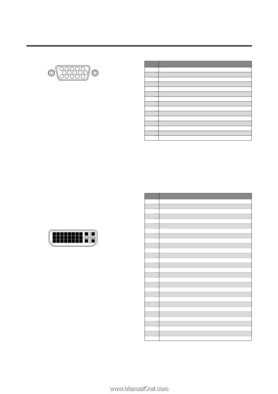
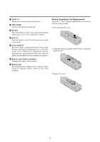
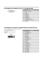
Pin Assignments and Signal Levels for 15 pin RGB (Analog) 5432 1 10 9 8 7 6 15 14 13 12 11 Pin No. 1 2 3 4 5 6 7 8 9 10 11 12 13 14 15 Signal (Analog) Red Green or sync-on-green Blue No connection Ground Red ground Green ground Blue ground No connection Sync signal ground No connection Bi-directional DATA (SDA) Horizontal sync or Composite sync Vertical sync Data clock Pin Configuration and Signal of the RGB 3 IN Connector (DVI Connector) The unit is equipped with a type of connector commonly used for both analog and digital. (Functionally, this cannot be used for an analog input.) (TMDS can be used for one link only.) RGB 3 12345678 9 10 11 12 13 14 15 16 17 18 19 20 21 22 23 24 25 26 27 28 29 Pin No. 1 2 3 4 5 6 7 8 9 10 11 12 13 14 15 16 17 18 19 20 21 22 23 24 25 26 27 28 29 Signal (Digital) T.M.D.S Data 2 T.M.D.S Data 2 + T.M.D.S Data 2 Shield No connection No connection DDC Clock DDC Data No connection T.M.D.S Data 1 T.M.D.S Data 1 + T.M.D.S Data 1 Shield No connection No connection +5V Power Ground Hot Plug Detect T.M.D.S Data 0 T.M.D.S Data 0 + T.M.D.S Data 0 Shield No connection No connection T.M.D.S Clock Shield T.M.D.S Clock + T.M.D.S Clock No connection No connection No connection No connection No connection 11
-
 1
1 -
2
-
3
-
4
-
5
-
6
-
7
-
8
-
9
-
10
-
11
-
12
-
 13
13 -
 14
14 -
 15
15 -
 16
16 -
 17
17 -
 18
18 -
 19
19 -
 20
20 -
 21
21 -
 22
22 -
 23
23 -
24
-
25
-
26
-
27
-
28
-
29
-
30
-
31
-
32
-
33
-
34
-
35
-
36
-
37
-
38
-
39
-
40
-
41
-
42
-
43
-
44
-
45
-
46
-
47
-
48
-
49
-
50
-
51
-
52
-
53
-
54
-
55
-
56
-
57
-
58
-
59
-
60
-
61
-
62
-
63
-
64
 |
 |