Netgear FS728TS FS752TS Hardware manual
Netgear FS728TS - ProSafe Smart Switch Manual
 |
UPC - 606449043600
View all Netgear FS728TS manuals
Add to My Manuals
Save this manual to your list of manuals |
Netgear FS728TS manual content summary:
- Netgear FS728TS | FS752TS Hardware manual - Page 1
FS700TS (728TS, 752TS, 752TPS) Series Hardware Installation Guide NETGEAR, Inc. 4500 Great America Parkway Santa Clara, CA 95054 USA 202-10333-01 October 2007 - Netgear FS728TS | FS752TS Hardware manual - Page 2
software upgrades. NETGEAR, INC. Support Information Phone: 1-888-NETGEAR, for US & Canada only. For other countries, see your Support information card. E-mail: [email protected] North American NETGEAR website: http://www.netgear.com Trademarks NETGEAR, the NETGEAR instructions Smart Switch gemäß - Netgear FS728TS | FS752TS Hardware manual - Page 3
operation and adverse action against the end-user by the applicable National regulatory authority. NOTE: This product's firmware limits operation to only the channels allowed in a particular Region or Country. Therefore, all options described in this user's guide may not be available in your version - Netgear FS728TS | FS752TS Hardware manual - Page 4
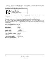
Consult the dealer or an experienced radio/TV technician for help. FS700TS Smart Switch with Gigabit Ports Tested to Comply with FCC Standards FOR HOME OR OFFICE made to the product, unless expressly approved by NETGEAR, Inc., could void the user's right to operate the equipment. D Canadian - Netgear FS728TS | FS752TS Hardware manual - Page 5
or Stack Master 2-33 Applying AC Power ...2-34 Managing the Switch using a Web Browser or the PC Utility for Initial Configuration ..2-34 Chapter 3 Physical Description Front and Back Panel Configuration 3-19 FS728TS Front and Back Panels 3-19 FS752TS Front and Back Panels 3-20 FS752TPS Front - Netgear FS728TS | FS752TS Hardware manual - Page 6
45 Ports ...3-25 SFP GBIC Module 3-26 Factory Defaults Button 3-26 Appendix A Troubleshooting Troubleshooting Chart A-1 Additional Troubleshooting Suggestions A-2 Network Adapter Cards A-2 Configuration ...A-2 Switch Integrity ...A-2 Auto-negotiation ...A-3 Appendix B Technical Specifications - Netgear FS728TS | FS752TS Hardware manual - Page 7
About This Guide Congratulations on the purchase of the NETGEAR Smart Switch. The NETGEAR® FS700TS Installation Manual describes how to install, configure and troubleshoot the smart switch. The information in this manual is intended for readers with intermediate computer and Internet skills. - Netgear FS728TS | FS752TS Hardware manual - Page 8
these specifications: Product Version Manual Publication Date FS700TS Smart Switch September 2007 Note: Product updates are available on the NETGEAR, Inc. web site at http://kbserver.netgear.com/main.asp. How to Use This Manual The HTML version of this manual includes the following: • Buttons - Netgear FS728TS | FS752TS Hardware manual - Page 9
top left of any page. - Click the Complete PDF Manual link at the top left of any page in the manual. The PDF version of the complete manual opens in a browser window. - Click the print icon in the upper left of the window. Tip: If your printer supports printing two pages on a single sheet of paper - Netgear FS728TS | FS752TS Hardware manual - Page 10
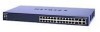
Package Contents" Overview This Installation Guide is for the following NETGEAR FS700TS Smart Switches: • FS728TS - This product offers support for 24 ports of 10/100 BaseT, 2 ports of 10/100/1000 BaseT, and 2 GbE combo (Copper/Fiber) ports. • FS752TS - This product offers support for 48 ports of 10 - Netgear FS728TS | FS752TS Hardware manual - Page 11
Graphical User Interface (GUI), you can view the switch's many features and use them in a simple and intuitive manner. The switch's management features include configuration for port and switch information, VLAN for traffic control, port trunking for increased bandwidth, and Class of Service (CoS - Netgear FS728TS | FS752TS Hardware manual - Page 12
identifies the key features of the NETGEAR Smart Switch. • 24/48 RJ-45 10/100 auto-sensing Giga switching ports. • 2-Port 10/100/1000M auto sensing Gigabit Ethernet switching ports. These ports are reserved for stacking units together, but can be configured as user ports. • Two Small Form-factor - Netgear FS728TS | FS752TS Hardware manual - Page 13
Guide The following SFP types are supported: • 1000Base-SX • 1000Base-LX • 100Base - FX • The devices support full Netgear Smart Switch to 4K Media Access Control (MAC) addresses. • Full- and half-duplex power supply. • Standard 1U high, rack mountable 19" chassis. • Fan speed control supported - Netgear FS728TS | FS752TS Hardware manual - Page 14
FS700TS Hardware Installation Guide Stacking Stacking provides multiple switch management through a single point as if all stack masters are a single unit. All stack masters are accessed through a single IP address through which the stack is managed. The stack can be managed from the following: • - Netgear FS728TS | FS752TS Hardware manual - Page 15
contains the following: • NETGEAR Smart Switch • Rubber footpads for tabletop installation • Power cord • Rack-mount Kit for installing the switch in a 19-inch rack • Installation Guide • Smart Switch Resource CD with SmartWizard Discovery and User's manual • Warranty/Support Information Card If any - Netgear FS728TS | FS752TS Hardware manual - Page 16
Stack Master" "Applying AC Power" "Managing the Switch using a Web Browser or the PC Utility for Initial Configuration" Preparing the Site Before installing the switch physically secure. The rack-mount kit supplied with the switch is also required. Locate the switch in a position that allows access - Netgear FS728TS | FS752TS Hardware manual - Page 17
Hardware Installation Guide Table 2-1. Site Requirements (continued) Characteristics Requirements Power source Environmental Provide a power source within 6 feet (1.8 meters) of the installation location. Power specifications for the switch are shown in Appendix A , "Troubleshooting". Ensure the - Netgear FS728TS | FS752TS Hardware manual - Page 18
Installation Guide 5. Tighten the screws with a #2 Phillips screwdriver to secure the switch in the rack. Figure 2-1 Note: Always install devices from the bottom of the to the top. This will prevent the rack from over balancing and toppling over. Checking the Installation Before applying power - Netgear FS728TS | FS752TS Hardware manual - Page 19
FS700TS Hardware Installation Guide Connecting Devices to the Switch The following procedure describes how to connect PCs to the switch's RJ-45 ports. The NETGEAR Smart Switch contains Auto Uplink™ technology, which allows you to attach devices using either straight-through or crossover cables. - Netgear FS728TS | FS752TS Hardware manual - Page 20
and slave designations are configured through automatic discovery. Manually changing the stacking configuration is through switch's web page once the device has been booted and is operational. For more information on stacking see the FS700TS Smart Switch User Guide. 2-33 v1.0, September 2007 - Netgear FS728TS | FS752TS Hardware manual - Page 21
called SmartWizard Discovery. For more information about managing the switch, see the Software Manual on the Smart Switch Resource CD. Note: When the device powers up, there is a default IP address already configured on the device. The default IP address is 192.168.0.239 and subnet mask 255.255 - Netgear FS728TS | FS752TS Hardware manual - Page 22
include: • "FS728TS Front and Back Panels" • "FS752TS Front and Back Panels" • "FS752TPS Front and Back Panels" • "LED Designations" • "Device Hardware Interfaces" Front and Back Panel Configuration FS728TS Front and Back Panels The NETGEAR FS728TS Smart Switch is a 24/48-Port 10/100M + 4-Port 10 - Netgear FS728TS | FS752TS Hardware manual - Page 23
the factory defaults. • Port LEDS • System LEDs Figure 3-2 illustrates the NETGEAR FS728TS Smart Switches back panel: Figure 3-2 The back panel contains the following: • A 100-240VAC/50-60 Hz universal input, which is a standard AC power receptacle for accommodating the supplied power cord. FS752TS - Netgear FS728TS | FS752TS Hardware manual - Page 24
Installation Guide • System LEDs Figure 3-4 illustrates the NETGEAR FS752TS Smart Switches back panel: Figure 3-4 The back panel contains the following: • A 100-240VAC/50-60 Hz universal input, which is a standard AC power receptacle for accommodating the supplied power cord. FS752TPS Front - Netgear FS728TS | FS752TS Hardware manual - Page 25
FS700TS Hardware Installation Guide Figure 3-6 illustrates the NETGEAR FS752TPS Smart Switch back panel: Figure 3-6 The back panel contains the following: • A 100-240VAC/50-60 Hz universal input, which is a standard AC power receptacle for accommodating the supplied power cord. LED Designations - Netgear FS728TS | FS752TS Hardware manual - Page 26
FS700TS Hardware Installation Guide Table 3-1. Port LEDS - Non-LED Devices (continued) Port LED Designation 4-Gigabits Copper Ports - Left LED Link/ACT/SPD Two LED's/Port on Jack LED: 2-SFP Ports - One LED/ Port Right LED Stack LED (Combo port group/ Copper port group): SFP Link/ACT LED • - Netgear FS728TS | FS752TS Hardware manual - Page 27
Mode (default). 1-24) • Solid Yellow - LED Mode in PoE LED Mode. Stack ID LED - One Seven segment LED Display • Off - the device is in standalone mode. • Green - Displays Stack ID (1-6). Stack Master LED • Off - Switch acts as a slave member in a stack of switches. • Solid Green - Switch acts - Netgear FS728TS | FS752TS Hardware manual - Page 28
FS700TS Hardware Installation Guide Table 3-3. System LEDs (continued) LED Power LED MAX POE LED Designation • Off - Power is disconnected. • Solid Green - Power is supplied to the switch and is operating normally. • Solid Yellow - Indicates that less than 180W of PoE power is available. • - Netgear FS728TS | FS752TS Hardware manual - Page 29
SFP GBIC module. Factory Defaults Button The Smart Switch has a Factory default button to enable clearing the current configuration and returning the device back to the factory settings. This removes all settings, including the password, VLAN settings and port configurations. Physical Description - Netgear FS728TS | FS752TS Hardware manual - Page 30
the NETGEAR Smart Switch. The topics include the following: • "Troubleshooting Chart" • "Additional Troubleshooting Suggestions" Troubleshooting Chart The following table lists symptoms, causes, and solutions of possible problems. Table A-1. Troubleshooting Chart Symptom Cause Solution Power - Netgear FS728TS | FS752TS Hardware manual - Page 31
If required, verify the integrity of the switch by resetting the switch. To reset the switch, disconnect the AC power from the switch and then reconnect AC source. If the problem continues, contact NETGEAR technical support. In North America, call 1-888-NETGEAR. If you are outside of North America - Netgear FS728TS | FS752TS Hardware manual - Page 32
not support auto negotiation, the switch only determines the speed correctly and the duplex mode defaults to half-duplex. The gigabit port on the Gigabit module negotiates speed, duplex mode, and flow control, provided that the attached device supports auto-negotiation. A-3 Troubleshooting v1 - Netgear FS728TS | FS752TS Hardware manual - Page 33
IEEE 802.3z 1000Base-X IEEE 802.3x flow control IEEE 802.3af (DTE Power via MDI) IEEE 802.1x IEEE 802.1D Management IEEE 802.1Q Static VLAN (Up to 128 ranging from 2 to 4K) IEEE 802.1p Class of Service (CoS) Port-based QoS (options High/Normal) Port Trunking LACP Interface 24 - Netgear FS728TS | FS752TS Hardware manual - Page 34
Gbps (for FS728TS) / 17.6 Gbps) Address database size: 4K media access control (MAC) addresses per system Mean Time Between Failure (MTBF): 100,000 hours for FS728TS, 84,000 hours for FS752TS Power Supply Maximum Power Consumption: FS728TS:17.4 W, FS752TS:22.3 W, FS752TPS:203 W. 100-240VAC/50-60 Hz - Netgear FS728TS | FS752TS Hardware manual - Page 35
FS700TS Hardware Installation Guide VCCI Class A C-Tick Electromagnetic Immunity EN 55022 (CISPR 22), Class A Safety CE mark, commercial UL listed (UL 1950) / CUL IEC950 / EN60950 Modules AGM731F 1000Base-SX - Netgear FS728TS | FS752TS Hardware manual - Page 36
of Service 1-2 Combo Port 2-10 Combo Ports 1-2 Connecting Devices to the Switch 4-16 Copper 1-1 Crossover 2-9 D Default IP Address 4-18 Default Reset Button 2-5, 2-7 Device Hardware Interfaces 2-9 Duplex Mode 2-9 E Example of Desktop Switching 3-12 F Factory Default Button 2-10 Factory Defaults - Netgear FS728TS | FS752TS Hardware manual - Page 37
IEEE 802.3z 1-2 IEEE Standards 1-2 IEEE-compliant 1-2 Installation Guide 1-4 Installing an SFP GBIC Module 4-16 Installing the Switch 4-14 Internal Power Supply 1-3 L LED Designations 2-8 Link/ACT LED 2-8 Low Latency 1-2 M MAC 1-3 MAX POE LED 2-9 Media Access Control 1-3 Mounting Holes 4-14 N Nylon - Netgear FS728TS | FS752TS Hardware manual - Page 38
User's Manual 1-4 UTP 4-16 V Ventilation 4-14 VLAN 1-1 W Warranty 1-4 Web-based Graphical User Interface 1-1 GS700TP Hardware Installation Guide v1.0, September 2007 Index-3 - Netgear FS728TS | FS752TS Hardware manual - Page 39
GS700TP Hardware Installation Guide Index-4 v1.0, September 2007
-
 1
1 -
 2
2 -
 3
3 -
 4
4 -
 5
5 -
 6
6 -
 7
7 -
8
-
9
-
10
-
11
-
12
-
13
-
14
-
15
-
16
-
17
-
18
-
19
-
20
-
21
-
22
-
23
-
24
-
25
-
26
-
27
-
28
-
29
-
30
-
31
-
32
-
33
-
34
-
35
-
36
-
37
-
38
-
39
 |
 |
202-10333-01
October 2007
NETGEAR
, Inc.
4500 Great America Parkway
Santa Clara, CA 95054 USA
FS700TS (728TS, 752TS,
752TPS) Series Hardware
Installation Guide