Netgear FS750AT FS750 Reference Manual
Netgear FS750AT - Modular Fast Ethernet Switch Manual
 |
UPC - 606449028058
View all Netgear FS750AT manuals
Add to My Manuals
Save this manual to your list of manuals |
Netgear FS750AT manual content summary:
- Netgear FS750AT | FS750 Reference Manual - Page 1
Modular Fast Ethernet Switch User's Guide MODEL FS 726 MODEL FS 750 - Netgear FS750AT | FS750 Reference Manual - Page 2
hereby certified that the NETGEAR Model FS726 Modular Fast Ethernet Switch and Model FS750 Modular Fast Ethernet Switch have been suppressed in to certain restrictions. Please refer to the notes in the operating instructions. Federal Office for Telecommunications Approvals has been notified of the - Netgear FS750AT | FS750 Reference Manual - Page 3
and, if not installed and used in accordance with the instructions, may cause harmful interference to radio communications. However, there This is to certify that the NETGEAR Model FS726 Modular Fast Ethernet Switch and Model FS750 Modular Fast Ethernet Switch are shielded against the generation of - Netgear FS750AT | FS750 Reference Manual - Page 4
NETGEAR system or with questions or problems following installation: • Check the NETGEAR Web page at http://www.NETGEAR.com. • Call Technical Support in North America at 1-888-NETGEAR on the Support Information Card that shipped with your switch. • E-mail Technical Support at [email protected]. - Netgear FS750AT | FS750 Reference Manual - Page 5
LED Mode Button and LED Descriptions 2-4 Module Bays 2-5 Auto Uplink 2-5 Reset Button 2-7 CHAPTER 3 Applications 3-1 Desktop Switching 3-1 Segment Switching and Bridging from 10 Mbps to 100 Mbps 3-2 Media Compatibility and Conversion 3-2 CHAPTER 4 Installation 4-1 Preparing the - Netgear FS750AT | FS750 Reference Manual - Page 6
CHAPTER 5 Troubleshooting Information 5-1 Additional Troubleshooting Suggestions 5-3 Network Adapter Cards 5-3 Configuration 5-3 Switch Integrity 5-3 Auto Negotiation 5-3 APPENDIX A Technical Specifications A-1 Network Protocol and Standards Compatibility A-1 Data Rate A-1 - Netgear FS750AT | FS750 Reference Manual - Page 7
APPENDIX C Cabling Guidelines C-1 Fast Ethernet Cable Guidelines C-1 Category 5 Cable C-2 Category 5 Cable Specifications C-3 Twisted Pair Cables C-3 Patch Panels and Cables C-5 Using 1000BASE-T Gigabit Ethernet over Category 5 Cable C-5 Overview C-5 Cabling C-6 Length C-6 - Netgear FS750AT | FS750 Reference Manual - Page 8
and Bridging 3-2 Figure 3-3. Example of Media Compatibility and Conversion 3-3 Figure 4-1. Attaching Mounting Brackets 4-3 Figure 4-2. Connecting Devices to the Switch 4-4 Figure B-1. RJ-45 Plug and RJ-45 Connector with Built-in LEDs B-1 Figure B-2 Duplex SC Cconnector and Duplex SC Plug - Netgear FS750AT | FS750 Reference Manual - Page 9
Table 1-1. Key Features 1-2 Table 2-1. Front Panel LEDs 2-4 Table 4-1. Site Requirements 4-2 Table 5-1. Troubleshooting Information 5-1 Table B-1. 10/100 Mbps RJ-45 Plug and RJ-45 Connector Pin Assignments B-2 Table B-2. 100/1000 Mbps RJ-45 Plug and RJ-45 Connector - Netgear FS750AT | FS750 Reference Manual - Page 10
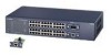
CHAPTER 1: INTRODUCTION This installation guide describes the NETGEAR FS726 and FS750 Modular Fast Ethernet Switches. NETGEAR's FS726 and FS750 are expandable, high-performance, IEEE-compliant network switches designed for users who require a large number of ports and want the high-speed capability - Netgear FS750AT | FS750 Reference Manual - Page 11
models support automatic address learning and IEEE 802.3x-compliant flow control to ensure optimal packet reliability. The FS726 and FS750 Switches can be free-standing or rack mounted in a wiring closet or equipment room. Features The following sections describe the characteristics of NETGEAR - Netgear FS750AT | FS750 Reference Manual - Page 12
and services • Store-and-forward intelligent processing to remove erroneous packets from the network • Automatic address-learning function to build the packet-forwarding information table. The table contains up to 8,000 media access control (MAC) addresses (that is, the switch can support networks - Netgear FS750AT | FS750 Reference Manual - Page 13
.3u Fast Ethernet standards, IEEE802.3ab Gigabit Ethernet, and IEEE802.3z Gigabit Ethernet. • LED indicators to show link, speed, activity, collision, and duplex for switch status and troubleshooting. • Rack Mount Kit for installing the switch in a standard 19-inch equipment rack introduction 1-4 - Netgear FS750AT | FS750 Reference Manual - Page 14
• Rubber footpads for tabletop installation • Power cord • Rack-mount kit for installing the switch in a 19-inch rack • NETGEAR FS726 and FS750 Modular Fast Ethernet Switch User's Guide • Support Information Card • Warranty & Owner Registration Card If any item is missing or damaged, contact your - Netgear FS750AT | FS750 Reference Manual - Page 15
button for alternating LED readout categories, Link LEDs, Mode LEDs, RJ-45 jacks, and two module bays for installing Gigabit Ethernet modules. Both the FS726 Switch and the FS750 Switch support Auto Uplink technology, eliminating the need for a Normal/Uplink push button. The back panel of each - Netgear FS750AT | FS750 Reference Manual - Page 16
Link LEDs Front Panel of the Model FS726 Switch Mode LEDs 10/100 Mbps ports Module Bays Power LED LED Mode Button Reset Button Rear Panel of the Model FS726 Switch Power Fan Receptacle Figure 2-1. Front and Back Panels of the FS726 Switch physical description 2-2 - Netgear FS750AT | FS750 Reference Manual - Page 17
10/100 Mbps ports: when you insert a cable into an RJ-45 port, the switch automatically detects the maximum speed (10 or 100 Mbps) and duplex mode (half- or next section). The 10/100 Mbps ports support only unshielded twisted-pair (UTP) cable terminated with an 8-pin RJ-45 plug. physical - Netgear FS750AT | FS750 Reference Manual - Page 18
Green Module Bay Port Green Mode in: Activity / Collision Green Yellow Mode in: FDX Green Yellow Activity On On Description Power is supplied to the switch. Power is disconnected Port has a valid link connection. A valid link has not been established on the port. On Port has made a 100 Mbps - Netgear FS750AT | FS750 Reference Manual - Page 19
(1000BASE-SX, NETGEAR Model AG711F) for high-speed connection to a server, to connect fiber and copper networks, or to extend your network backbone with high-speed links. Auto Uplink To simplify the procedure for attaching devices, all RJ-45 ports on the FS726 and FS750 Switches support Auto Uplink - Netgear FS750AT | FS750 Reference Manual - Page 20
Model FS726 Switch FR314 Router Figure 2-3. Creating Redundant Paths between Network Devices (Example 1) EN524 Hub Model FS726 Switch FR314 Router Figure 2-4. Creating Redundant Paths between Network Devices (Example 2) physical description 2-6 - Netgear FS750AT | FS750 Reference Manual - Page 21
module from a module bay. To activate the Reset button, insert a small wire, such as a paper clip, into the hole and gently push. As the switch reinitializes, all of the LEDs will extinguish, then light up for approximately one second during the self-test, and then return to their normal state. - Netgear FS750AT | FS750 Reference Manual - Page 22
or used with 10 Mbps hubs, 100 Mbps hubs, or 10/100 Mbps switches. This chapter shows how the FS726 and FS750 Switches can be used in various network environments. Topics include: • Desktop switching • Segment switching and bridging from 10 Mbps to 100 Mbps • Media compatibility and conversion - Netgear FS750AT | FS750 Reference Manual - Page 23
models can segment networks that are built with the NETGEAR DS508 and EN516 hubs, and can act as bridges connecting traditional 10BASE-T Ethernet networks to 100BASE-TX Fast Ethernet networks. Model FS726 Switch Model DS508 Hub Model FR314 Router Model EN516 Hub Figure 3-2. Example of Segment - Netgear FS750AT | FS750 Reference Manual - Page 24
On = Link 8 Normal/Uplink 17 1000M 100M 16 18 MODEL FS518T Model FS509 9PORT Fast 10/100Mbps Ethernet Switch Power Rx/Tx 1 234 5 678 9 Green = FDX, Yellow = COL 100M 1 10M 2 3 4 5 6 7 8 On = Link Normal/Uplink 1 Ethernet MODEL FS509 Tx Rx 1000M Link Figure 3-3. Example - Netgear FS750AT | FS750 Reference Manual - Page 25
CHAPTER 4: INSTALLATION This chapter describes the installation procedures for the NETGEAR FS726 and FS750 Switches. Topics include: • Preparing the site • Installing the switch • Connecting devices to the switch • Checking the installation • Applying AC power installation 4-1 - Netgear FS750AT | FS750 Reference Manual - Page 26
(48.3-centimeter) EIA standard equipment rack that is grounded and physically secure. You also need the rack-mount kit supplied with your switch. Access Locate the switch in a position that lets you access the front panel RJ-45 ports, view the front panel LEDs, and access the rear-panel stacking - Netgear FS750AT | FS750 Reference Manual - Page 27
Switch You can install the NETGEAR FS726 and FS750 Switches on a flat surface or in a standard 19-inch rack. Installing the Switch on a Flat Surface 1. The switch ships with four self-adhesive rubber footpads. Affix one rubber footpad on each of the four concave spaces on the bottom of the switch - Netgear FS750AT | FS750 Reference Manual - Page 28
RJ-45 ports. When attaching devices to an FS726 or an FS750, the switch's support for Auto Uplink technology allows you to attach devices using either straight-through or crossover cables (for more information about Auto Link' technology, refer to " - Netgear FS750AT | FS750 Reference Manual - Page 29
Using Gigabit Ethernet Modules The modularity of the FS726 and 750 Switches provides you with a highly adaptable network.. You not only can configure your network for copper and/or fiber gigabit uplinks, but you also can opt - Netgear FS750AT | FS750 Reference Manual - Page 30
and that the power source is good. If this does not resolve the problem, refer to Chapter 5, Troubleshooting. When power is applied, the switch conducts a power-on self-test (POST) to verify operation. After the switch passes the POST, it is functional and ready to pass data. installation 4-6 - Netgear FS750AT | FS750 Reference Manual - Page 31
installation 4-7 - Netgear FS750AT | FS750 Reference Manual - Page 32
guidance in troubleshooting the NETGEAR FS726 and FS750 Switches. Information includes: • Troubleshooting information table • Additional troubleshooting suggestions Troubleshooting Chart Table 5-1 lists symptoms, causes, and solutions of possible problems. Table 5-1. Troubleshooting Chart Symptom - Netgear FS750AT | FS750 Reference Manual - Page 33
and configured correctly. File transfer is slow or performance degradation is a problem. Half- or full-duplex setting on the switch and the connected device are not the same. Make sure the attached only one path from any networked device to any other networked device. troubleshooting 5-2 - Netgear FS750AT | FS750 Reference Manual - Page 34
Integrity If required, verify the integrity of the switch by resetting the switch. To reset the switch, remove AC power from the switch and then reapply AC power. If the problem continues, contact NETGEAR technical support. In North America, call 1-888-NETGEAR. If you are outside of North America - Netgear FS750AT | FS750 Reference Manual - Page 35
APPENDIX A: TECHNICAL SPECIFICATIONS This appendix provides technical specifications for the NETGEAR FS726 or FS750 Switches. Network Protocol and Standards Compatibility ISO/IEC 802-3i 10BASE-T IEEE 802.3u 100BASE-TX IEEE 802.3ab 1000BASE-T IEEE 802.3z 1000BASE-SX IEEE - Netgear FS750AT | FS750 Reference Manual - Page 36
microseconds for 64-byte frames in store-andforward mode for 10 Mbps to 100 Mbps transmission Address database size: 8,000 media access control (MAC) addresses per system Addressing: 48-bit MAC address Acoustic noise: (ANSI-S10.12) FS726 45 dB FS750 52dB Heat Dissipation: FS726 FS750 18.99 - Netgear FS750AT | FS750 Reference Manual - Page 37
Electrical Specifications Power Consumption: FS726 40W maximum FS750 60W maximum Physical Specifications Dimensions: Weight: FS726 W 440 mm (17.3") D 205 mm (8.1") H 43 mm (1.6") 3.2 Kg (7.0 lbs) FS750 W 440 mm (17.3") D 205 mm (8.1") H 86 mm (3.4") 4.3 Kg (9.5 lbs) Environmental - Netgear FS750AT | FS750 Reference Manual - Page 38
Electromagnetic Emissions Meets requirements of: CE mark, commercial FCC Part 15, Subpart B, Class A EN 55024 (CISPR 22), Class A VCCI Class 1A C-tick Electromagnetic Susceptibility CE mark, commercial Electrostatic discharge (ESD): IEC 801-2, Level 2/3 Radiated electromagnetic field: IEC 801-3, - Netgear FS750AT | FS750 Reference Manual - Page 39
-45 plug and the RJ-45 connector used for the NETGEAR FS726 and FS750 Switches. RJ-45 Plug and RJ-45 Connector In a Fast connector. The RJ-45 connector is used to connect stations, hubs, and switches through UTP cable; it supports 10 Mbps, 100 Mbps, or 1000 Mbps data transmission. Figure B-1 shows - Netgear FS750AT | FS750 Reference Manual - Page 40
Table B-1 lists the pin assignments for the 10/100 Mbps RJ-45 plug and the RJ-45 connector. Table B-1. 10/100 Mbps RJ-45 Plug and RJ-45 Connector Pin Assignments Pin 1 2 3 6 4, 5, 7, 8 Normal Assignment Uplink Assignment Input Receive Data + Output Transmit Data + Input Receive Data - Output - Netgear FS750AT | FS750 Reference Manual - Page 41
Duplex SC Plug and Duplex SC Connector The duplex SC connector connects stations, hubs, and switches that support the 1000BASE-SX fiber interface. Each fiber link needs a clearly defined, external crossover. In other words, the transmit port of one interface must be wired - Netgear FS750AT | FS750 Reference Manual - Page 42
APPENDIX C: CABLING GUIDELINES This appendix provides specifications for cables used with the FS726 and FS750 Switches. Fast Ethernet Cable Guidelines Fast Ethernet uses UTP cable, as specified in the IEEE 802.3u standard for 100BASE-TX. The specification requires Category 5 UTP - Netgear FS750AT | FS750 Reference Manual - Page 43
Category 5 Cable Category 5 distributed cable that meets ANSI/EIA/TIA-568-A building wiring standards can be a maximum of 328 feet (ft) or 100 meters (m) in length, divided as follows: • 20 ft (6 m) between the hub and the patch panel (if used) • 295 ft (90 m) from the wiring closet to the wall - Netgear FS750AT | FS750 Reference Manual - Page 44
in the device. Computers and workstation adapter cards are usually media-dependent interface ports, called MDI or uplink ports. Most repeaters and switch ports are configured as media-dependent interfaces with built-in crossover ports, called MDI-X or normal ports. Auto UplinkTM automatically senses - Netgear FS750AT | FS750 Reference Manual - Page 45
3 Rx 6 1 Rx 2 B 3 Tx 6 Key: 736EA A = Uplink or MDI port (as on a PC) B = Normal or MDI-X port (as on a hub or switch) 1, 2, 3, 6 = Pin numbers Figure C-1. Straight-Through Twisted-Pair Cable Figure C-2 illustrates crossover twisted pair cable. 1 Rx 2 B 3 Tx 6 1 Rx 2 B 3 Tx 6 Key: 737EA - Netgear FS750AT | FS750 Reference Manual - Page 46
you are using patch panels, make sure that they meet the 100BASE-TX requirements. NETGEAR recommends Category 5 UTP cable for all patch cables and work area cables to ensure implemented. The following sections are designed to act as a guide to correct cabling for 1000BASE-T. cabling guidelines C-5 - Netgear FS750AT | FS750 Reference Manual - Page 47
Cabling The 1000BASE-T product is designed to operate over Category 5 cabling. To further enhance the operation, the cabling standards have been amended. The latest standard is Category 5e, which defines a higher level of link performance than is available with Category 5 cable. If installing new - Netgear FS750AT | FS750 Reference Manual - Page 48
Factors that affect the return loss are: • The number of transition points, as there is a connection via an RJ-45 to another connector, a patch panel, or device at each transition point. • Removing the jacket that surrounds the four pairs of twisted cable. It is highly recommended that, when RJ-45 - Netgear FS750AT | FS750 Reference Manual - Page 49
Fiber Optic Cables In North America, use EIA-569-A horizontal 62.5/125 µm multimode optical fiber cable (ANSI/EIA/TIA-492AAAA). Internationally, use ISO/IEC 11801 62.5/125 µm multimode optical fiber cable (IEC 793-2 type A1b, with 1.0db/km attenuation and 500 MHz/km bandwidth). Refer to Table C-2 - Netgear FS750AT | FS750 Reference Manual - Page 50
Patch Cables, C-7 Conclusion, C-7 Checking the Installation, 4-6 Connecting Devices to the Switch, 4-4 Connector pin assignments RJ-45 Plug and RJ-45 Connector, B-1 Customer Support, iv D Data Rate, A-1 Desktop Switching, 3-1 F Fast Ethernet Cable Guidelines, C-1 Features, 1-2 Front and Back Panels - Netgear FS750AT | FS750 Reference Manual - Page 51
Return Loss, C-6 RJ-45 Plug and RJ-45 Connector, B-1 S Segment Switching and Bridging from 10Mbps to 100 Mbps, 3-2 T Technical Specifications Network Protocol Troubleshooting Troubleshooting Chart, 5-1 Additional Troubleshooting Suggestions, 5-3 Network Adapter Cards, 5-3 Configuration, 5-3 Switch - Netgear FS750AT | FS750 Reference Manual - Page 52
NETGEAR, Inc. 4500 Great America Parkway Santa Clara, CA 95054 USA Phone: 1-888-NETGEAR www.NETGEAR.com M-FS700NA-0 July 2001
-
 1
1 -
 2
2 -
 3
3 -
 4
4 -
 5
5 -
 6
6 -
 7
7 -
8
-
9
-
10
-
11
-
12
-
13
-
14
-
15
-
16
-
17
-
18
-
19
-
20
-
21
-
22
-
23
-
24
-
25
-
26
-
27
-
28
-
29
-
30
-
31
-
32
-
33
-
34
-
35
-
36
-
37
-
38
-
39
-
40
-
41
-
42
-
43
-
44
-
45
-
46
-
47
-
48
-
49
-
50
-
51
-
52
 |
 |

FS
MODEL
726
FS
MODEL
750
Modular Fast Ethernet Switch
User‘s Guide