Netgear GS748Tv5 Hardware Installation Guide
Netgear GS748Tv5 Manual
 |
View all Netgear GS748Tv5 manuals
Add to My Manuals
Save this manual to your list of manuals |
Netgear GS748Tv5 manual content summary:
- Netgear GS748Tv5 | Hardware Installation Guide - Page 1
GS716T, GS724T and GS748T Gigabit Smart Switch Hardware Installation Guide September 2013 202-11329-01 350 East Plumeria Drive San Jose, CA 95134 USA - Netgear GS748Tv5 | Hardware Installation Guide - Page 2
GS716T, GS724T and GS748T Gigabit Smart Switch 2 - Netgear GS748Tv5 | Hardware Installation Guide - Page 3
. To register your product, get the latest product updates, get support online, or for more information about the topics covered in this manual, visit the Support website at http://support.netgear.com Phone (US & Canada only): 1-888-NETGEAR Phone (Other Countries): Check the list of phone numbers - Netgear GS748Tv5 | Hardware Installation Guide - Page 4
GS716T, GS724T and GS748T Gigabit Smart Switch 4 - Netgear GS748Tv5 | Hardware Installation Guide - Page 5
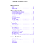
8 GS716T/GS724T Back Panel Configuration 9 GS748T Front Panel Configuration 10 GS748T Back Panel Configuration 10 LED Designations 11 Port LEDs 11 System LEDs 12 Device Hardware Interfaces 13 RJ-45 Ports 13 SFP GBIC Module 13 Factory Defaults Button 13 Chapter 3 Applications Desktop - Netgear GS748Tv5 | Hardware Installation Guide - Page 6
GS716T, GS724T and GS748T Gigabit Smart Switch Appendix B Technical Specifications Appendix C Notification of Compliance 2 - Netgear GS748Tv5 | Hardware Installation Guide - Page 7
the purchase of the GS716T,GS724T,GS748T Series Smart Switch. This NETGEAR Smart Switch is a state-of-the-art, high-performance, GS716Tv3, GS724Tv4, GS748Tv5 Cost Down Hardware Installation Guide describes how to install and power on the Smart Switch. The information in this manual is intended for - Netgear GS748Tv5 | Hardware Installation Guide - Page 8
Guide is for the following NETGEAR Smart Switches: • GS716Tv3 - This product offers support for 16 ports of 10/100/1000 Mbps and two Form-factor slots, which support configuration for port and switch information, VLAN for traffic control, port trunking for increased bandwidth, IPv6 Management support - Netgear GS748Tv5 | Hardware Installation Guide - Page 9
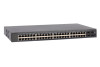
fiber ports. • GS748Tv5 has 48 10/100/1000Mbps ethernet copper port, 2 Combo ports and 2 dedicated 1000Mbps fiber ports. • The following SFP types are supported: • 1000BASE-SX • 1000BASE-LX • 100BASE-FX (for combo ports on GS748T only) • The devices support full NETGEAR Smart Switch functionality - Netgear GS748Tv5 | Hardware Installation Guide - Page 10
Switch Package Contents Figure 1 shows the package contents of the NETGEAR GS716Tv3 and GS724Tv4 and GS748Tv5 Series Smart Switch. Reset PWR ProSafe 24 Port 10/100/1000 Mbps Smart Switch Link/ACT SPD Green(1000M) Yellow(100M) FDX Link/ACT SPD FDX Figure 1. Package Contents Verify that the - Netgear GS748Tv5 | Hardware Installation Guide - Page 11
Description This chapter describes the NETGEAR Smart Switch hardware features. Topics include: • GS716T/GS724T Front Panel Configuration • GS716T/GS724T Back Panel Configuration • GS748T Front Panel Configuration • GS748T Back Panel Configuration • LED Designations • Device Hardware Interfaces - Netgear GS748Tv5 | Hardware Installation Guide - Page 12
and negotiating the operation duplex mode with the link partner automatically Figure 2 illustrates the NETGEAR GS716T Smart Switch front panel: Reset PWR System LEDs ProSafe 16 Port 10/100/1000Mbps Smart Switch Link/ACT SPD Green(1000M) Yellow(100M) FDX Link/ACT SPD FDX 10/100/1000 Mbps - Netgear GS748Tv5 | Hardware Installation Guide - Page 13
GS716T, GS724T and GS748T Gigabit Smart Switch GS716T/GS724T Back Panel Configuration Figure 4 illustrates the NETGEAR GS716T/GS724T Smart Switch back panel: 100-240V ~ 50-60Hz Power Connector Figure 4. GS716T/GS724T Back Panel The back panel contains the following: • A 100-240VAC/ - Netgear GS748Tv5 | Hardware Installation Guide - Page 14
to restart the device. • Recessed default reset button to restore the device back to the factory defaults. • Link, Speed, and Activity LEDs for each port • Power and FAN status LED GS748T Back Panel Configuration Figure 6 illustrates the NETGEAR GS748T Smart Switch back panel: Figure 6. GS748T - Netgear GS748Tv5 | Hardware Installation Guide - Page 15
is established on the port. • Flashing Green - Packet transmission or reception is occurring on the port at 1000 Mbps. • Solid Yellow - A valid 10/100 Mbps link is established on the port. • Flashing Yellow - Packet transmission or reception is occurring on the port at 10/100 Mbps. • Off - No 10/100 - Netgear GS748Tv5 | Hardware Installation Guide - Page 16
48 changes to SFP, the port LED for copper ports 47 and 48 changes to off. • Off - No SFP module link is established • Solid Green - A valid 1000 Mbps SFP module link is established. • Blinking Green - The port is transmitting or receiving packets at 1000 Mbps. • Solid Yellow - A valid 100 Mbps SFP - Netgear GS748Tv5 | Hardware Installation Guide - Page 17
support NETGEAR Factory Defaults Button The Smart Switch has a Factory Default button so that you can remove the current configuration and return the device to its factory settings. When you enable the Factory Default button, all settings, including the password, VLAN settings and port configurations - Netgear GS748Tv5 | Hardware Installation Guide - Page 18
3. Applications 3 Your NETGEAR GS716Tv3 and GS724Tv4 and GS748Tv5 Gigabit Smart Switch is designed to provide flexibility in configuring your network connections. It can be used as a stand-alone device or with 10 Mbps, 100 Mbps, and 1000 Mbps hubs and switches. 14 - Netgear GS748Tv5 | Hardware Installation Guide - Page 19
GS716Tv3 and GS724Tv4 and GS748Tv5 Gigabit Smart Switch Desktop Switching The NETGEAR Smart Switch can be used as a desktop can provide 2000 Mbps throughput. Reset PWR ProSafe 24 Port 10/100/1000 Mbps Smart Switch Link/ACT SPD Green(1000M) Yellow(100M) FDX Link/ACT SPD FDX Figure 7. - Netgear GS748Tv5 | Hardware Installation Guide - Page 20
GS716Tv3 and GS724Tv4 and GS748Tv5 Gigabit Smart Switch GS748T GS748T 1 2 3 4 5 6 SFP LED GREEN= 1000Mbps 47F 49 Blink=ACT Reset Power LED Link/Act Mode Green=Link at 1000M Yellow=Link at 100/10M Blink=ACT 48F 50 Factory Default Model GS108T Model FS728TP ` ` Figure 8. - Netgear GS748Tv5 | Hardware Installation Guide - Page 21
4. Installation 4 This chapter describes the installation procedures for your NETGEAR GS716T,GS724T and GS748T Series Smart Switch. Switch installation involves the following steps: Step 1: Prepare the Site Step 2: Install the Switch Step 3: Check the Installation - Netgear GS748Tv5 | Hardware Installation Guide - Page 22
source Provide a power source within 6 feet (1.8 meters) of the installation location. Power specifications for the switch are shown in GS716T/GS724T Back Panel Configuration Ensure the AC outlet is not controlled by a wall switch, which can accidentally turn off power to the outlet and the switch - Netgear GS748Tv5 | Hardware Installation Guide - Page 23
GS716T, GS724T and GS748T Gigabit Smart Switch Step 2: Install the Switch The NETGEAR GS716T,GS724T,GS748T Series Smart Switch can be installed on a flat surface or in a standard 19-inch rack. Install the Switch on a Flat Surface The - Netgear GS748Tv5 | Hardware Installation Guide - Page 24
GS716T, GS724T and GS748T Gigabit Smart Switch Step 3: Check the Installation Before applying power perform the following: • Inspect the equipment thoroughly. • Verify that all cables are installed correctly. • Check cable routing to make sure cables are not damaged or creating a safety hazard. • - Netgear GS748Tv5 | Hardware Installation Guide - Page 25
switch's RJ-45 ports. The NETGEAR GS716T,GS724T,GS748T Series Smart Switch contains Auto Uplink™ technology, which allows the attaching of devices using either straight-through or crossover cables. Reset PWR ProSafe 24 Port 10/100/1000 Mbps Smart Switch Link/ACT SPD Green(1000M) Yellow(100M - Netgear GS748Tv5 | Hardware Installation Guide - Page 26
GS716T, GS724T and GS748T Gigabit Smart Switch Step 5: Install an SFP GBIC Module The following procedure describes how to install an SFP Gigabit Ethernet module in the switch's Gigabit module bay. Standard SFP GBIC modules are sold separately from the Smart Switch. If an SFP GBIC module is not - Netgear GS748Tv5 | Hardware Installation Guide - Page 27
GS716T, GS724T and GS748T Gigabit Smart Switch Step 6: Apply AC Power NETGEAR GS716T,GS724T,GS748T Series Smart Switch does not have an ON/OFF switch. The method plugged in correctly and that the power source is good. If this does not resolve the problem, refer to Table 5, Troubleshooting Chart. 23 - Netgear GS748Tv5 | Hardware Installation Guide - Page 28
Control Center Utility The NETGEAR GS716T,GS724T,GS748T Series Smart management software enables the setup of VLAN and Trunking features, and also Manual on the Smart Switch Resource CD. Note: When the device powers up, there is a default IP address already configured on the device. The default IP - Netgear GS748Tv5 | Hardware Installation Guide - Page 29
A. Troubleshooting This chapter provides information about troubleshooting the NETGEAR Smart Switch. Topics include the following: • Troubleshooting Chart • Additional Troubleshooting Suggestions A 25 - Netgear GS748Tv5 | Hardware Installation Guide - Page 30
problems. Table 5. Troubleshooting Chart Symptom Cause Solution Power LED is off. No power is received. Check the power cord connections for the switch at the switch and the connected device. Ensure all cables used are correct and comply with Ethernet specifications. Link - Netgear GS748Tv5 | Hardware Installation Guide - Page 31
If required, verify the integrity of the switch by resetting the switch. To reset the switch, remove the AC power from the switch and then reapply AC power. If the problem continues, contact NETGEAR technical support. In North America, call 1-888-NETGEAR. If you are outside of North America, please - Netgear GS748Tv5 | Hardware Installation Guide - Page 32
8.0 ~ 9.0, Firefox 20 or 21 IEEE 802.1Q VLAN IEEE 802.3ad Link Aggregation IEEE 802.1D Spanning Tree Protocol IEEE 802.1W Rapid Multicast Vlan Registration IEEE 802.1x (RAIDUS), Dynamic Vlan Assignment Storm control for broadcast, multicast and unknown unicast packets IEEE 802.1p Class of Service - Netgear GS748Tv5 | Hardware Installation Guide - Page 33
Persistent log supported Port Locking Denial of Service Protection (control plane) Denial of Service Protection (data plane) TACACS+ RADIUS EAPOL Forwarding BPDU Flooding Auto VoIP Auto Video Auto DoS ACL Wizard Management Security Smart Control Center Discovery Boot code update Password management - Netgear GS748Tv5 | Hardware Installation Guide - Page 34
ID configuration Authentication login lists IPv4 and IPv6 DiffServ MAC, IPv4 and IPv6 ACL Dual Image Support SNTP (Simple Network Time Protocol) 2 servers. Disabled by default. Interface GS716Tv3/GS724Tv4 • 16/24 10/100/1000Mbps ethernet copper ports • 2 dedicated 1000Mbps fiber ports GS748Tv5 • 48 - Netgear GS748Tv5 | Hardware Installation Guide - Page 35
GS716T, GS724T and GS748T Gigabit Smart Switch Power Supply GS716T/GS724T: 100-240V~, 50/60Hz, 1.0A Max, universal input GS748T: 100-240V~, 50/60Hz, 1.5A Max, universal input Physical Specifications GS716T: Dimensions (H x W x D): 43 x 440 x 204 (mm) Weight: 2.57 kg GS724T: Dimensions (H x W x D): - Netgear GS748Tv5 | Hardware Installation Guide - Page 36
GS716T, GS724T and GS748T Gigabit Smart Switch UL listed (UL 1950)/cUL IEC950/EN60950 CB and CCC Modules AGM731F 1000BASE-SX SFP GBIC for multimode fiber AGM732F 1000BASE-LX SFP GBIC for single mode fiber AGM733 1000BASE-LZ GBIC for long haul single mode fiber 32 - Netgear GS748Tv5 | Hardware Installation Guide - Page 37
firmware limits operation to only the channels allowed in a particular Region or Country. Therefore, all options described in this user's guide may conjunction with any other antenna or transmitter. FCC Declaration Of Conformity We, NETGEAR, Inc., 350 East Plumeria Drive, San Jose, CA 95134, declare - Netgear GS748Tv5 | Hardware Installation Guide - Page 38
. FCC Radio Frequency Interference Warnings & Instructions This equipment has been tested and found product, unless expressly approved by NETGEAR, Inc., could void the user 2004/108/EC and Low Voltage Directive 2006/95/EC as supported by applying the following test methods and standards: • EN55022: - Netgear GS748Tv5 | Hardware Installation Guide - Page 39
5 Brackets 19 C Category 5 Unshielded Twisted-Pair 4 Checking the Installation 20 Class of Service 4 compliance 33 Connecting Devices to the Switch 21 Copper 4 Crossover 13 D Default IP Address 24 Default Reset Button 8, 10 Device Hardware Interfaces 8 Duplex Mode 13 E Example of Desktop Switching - Netgear GS748Tv5 | Hardware Installation Guide - Page 40
Switch F Factory Default Button 13 Factory Defaults 8, 10 Fiber Connectivity 4 Flat Surface 19 Full-duplex 4 G GBIC 4, 13 Gigabit Ports 4 H High-speed Servers 4 Hz 9, 11 I IEEE 802.3ab 5 IEEE 802.3i 5 IEEE 802.3u 5 IEEE 802.3x 5 IEEE 802.3z 5 IEEE Standards 5 IEEE-compliant 4 Installation Guide - Netgear GS748Tv5 | Hardware Installation Guide - Page 41
Reset Button 8, 10 RJ-45 4 RJ-45 Ports 13 Rubber footpads 6, 19 S SFP GBIC Module 13 SFP LINK/ACT Support Information Card 6 System LEDs 12 T technical support 3 Temperature 18 trademarks 3 Traffic Control 4 Troubleshooting Chart 26 U User Intervention 13 User's Manual 6 UTP 21 V Ventilation 18 VLAN - Netgear GS748Tv5 | Hardware Installation Guide - Page 42
GS716T, GS724T and GS748T Gigabit Smart Switch W Warranty 6 Web-based Graphical User Interface 4 38
-
 1
1 -
 2
2 -
 3
3 -
 4
4 -
 5
5 -
 6
6 -
 7
7 -
8
-
9
-
10
-
11
-
12
-
13
-
14
-
15
-
16
-
17
-
18
-
19
-
20
-
21
-
22
-
23
-
24
-
25
-
26
-
27
-
28
-
29
-
30
-
31
-
32
-
33
-
34
-
35
-
36
-
37
-
38
-
39
-
40
-
41
-
42
 |
 |

350 East Plumeria Drive
San Jose, CA 95134
USA
September 2013
202-11329-01
GS716T, GS724T and GS748T
Gigabit Smart Switch
Hardware Installation Guide