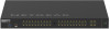
Netgear GSM4248P Installation Guide
Netgear GSM4248P Manual
 |
View all Netgear GSM4248P manuals
Add to My Manuals
Save this manual to your list of manuals |
Netgear GSM4248P manual content summary:
- Netgear GSM4248P | Installation Guide - Page 1
to as the service port), through any firmware, visit netgear.com/support/download/. NOTE: For information about using the main UI or AV UI, including information about assigning a static IP address to the switch, see the one of the user manuals, which you can download by visiting netgear.com/support - Netgear GSM4248P | Installation Guide - Page 2
about CLI management, see the CLI reference manual, which you can download by visiting netgear.com/support/download/. Find the IP address assigned by the IP address of the OOB port (which is also referred to as the service port), type the show serviceport command, and press Enter. • To find the
-
 1
1 -
 2
2
 |
 |
Installation Guide
AV Line of Fully Managed Switches
M4250 Series
1.
Install the switch using one of the following methods:
•
On a flat surface
. Attach one of the rubber footpads that came with the switch
on each of the four concave spaces on the bottom of the switch.
•
In a rack
. Except for desktop models, use the rack-mount kit that is supplied with
your switch.
•
Attached to a flat surface or under a table
. For desktop models only, use the
brackets that are supplied with your switch.
2.
Apply power.
The Power LED lights solid yellow while the switch conducts a power-on self-test
(POST). After the POST completes, the Power LED indicates the results:
•
Solid green
. The switch is functional.
•
Solid yellow
. The POST failed.
If the Power LED does not light at all, check to see that the power cable or power
adapter is plugged in correctly and that the power source is functioning.
3.
Connect devices to the switch.
NOTE:
If purchased, SFP modules and cables are shipped separately.
We recommend using the following cables and, if applicable, SFP modules:
•
Category 5e (Cat 5e) or better cable for a copper port at 1 Gbps or 2.5 Gbps.
•
NETGEAR AGM734 module for a copper port at 1 Gbps.
•
NETGEAR AGM731F or AGM732F module for a fiber port at 1 Gbps.
•
NETGEAR AXM761, AXM762, AXM763,
AXM764, or AXM765 module for a fiber port
at 10 Gbps.
•
NETGEAR AXC761 (1 m), AXC763 (3 m),
AXC765 (5 m), AXC767 (7 m),
AXC7610 (10 m), AXC7615 (15 m), or AXC7620 (20 m) cable for a fiber port.
This switch is designed for indoor use only. If you want to connect it to a device located
outdoors, the outdoor device must be properly grounded and surge protected, and you
must install an Ethernet surge protector inline between the switch and the outdoor device.
Failure to do so can damage the switch.
Before connecting this switch to outdoor cables or devices, see
https://kb.netgear.com/000057103 for safety and warranty information.
NOTE:
For information about using the main UI or AV UI, including information
about assigning a static IP address to the switch, see the one of the user manuals,
which you can download by visiting netgear.com/support/download/.
NOTE:
Make sure that the switch is running the latest firmware version.
To download firmware, visit
netgear.com/support/download/.
NOTE:
For more information about these requirements, the hardware setup
process, the LEDs, and how to connect devices, see the hardware installation
guide, which you can download by visiting netgear.com/support/download/.
Set up the switch
Prepare the installation site so that mounting, access, power source, and environmental
requirements are met.
Log in and configure the switch
You can log in and configure the switch through the out-of-band (OOB) port (which is also
referred to as the service port), through any Ethernet network port, or through a console
port. By default, the switch functions as a DHCP client.
To log in and configure the switch, use
one
of the following methods:
•
Audio-video local browser user interface
:
Use the audio-video local browser user
interface, abbreviated as AV UI, through the OOB port or any Ethernet network port
(see
Access the AV UI or main UI to configure the switch
).
•
Main local browser user interface
: Use the main local browser user interface,
abbreviated as main UI, through the OOB port or any Ethernet network port (see
Access the AV UI or main UI to configure the switch
).
•
CLI
: Use the command-line interface (CLI) through the Type-C USB console port or
RJ-45 RS232 console port. You can configure the IP address manually or use the
ezconfig utility (see Access the CLI to configure the switch
).
Access the AV UI or main UI to configure the switch
You can use a computer on the same subnet as the switch to access either the AV UI or
main UI over the switch’s default IP address.
1.
Configure your computer with a static IP address:
•
For access over an Ethernet network port, use an IP address in the 169.254.0.0
subnet with subnet mask 255.255.0.0. For example, use 169.254.100.201.
•
For access over the OOB port, use an IP address in the 192.168.0.0 subnet with
subnet mask 255.255.255.0. For example, use 192.168.0.201.
2.
Connect an Ethernet cable from an Ethernet port on your computer to the OOB port
or an Ethernet network port on the switch:
3.
Launch a web browser and enter the default IP address of the switch in the address
field of the browser:
•
Ethernet port
: For access over an Ethernet network port, enter
.
•
OOB port
: For access over the OOB port, enter
.
The login page displays.
4.
To log in for the first time, do one of the following:
•
AV UI
: To access the AV UI, enter
admin
for the user name, leave the password
field blank, and click the
AV UI Login
button.
•
Main UI
: To access the main UI, click the
Main UI Login
button. The main UI login
page displays. Enter
admin
for the user name, leave the password field blank,
and click the
Login
button.
On first login, you are required to specify a password.
5.
Specify a password and log in again using your new password.
6.
Configure the switch settings.
On each UI page, if you make changes, be sure to save the changes.