Netgear JFS524E-100NAS Installation Guide
Netgear JFS524E-100NAS - Prosafe 24PORT 10/100 Manual
 |
UPC - 606449066388
View all Netgear JFS524E-100NAS manuals
Add to My Manuals
Save this manual to your list of manuals |
Netgear JFS524E-100NAS manual content summary:
- Netgear JFS524E-100NAS | Installation Guide - Page 1
JFS524E_IG_12Aug09.fm Page 1 Wednesday, August 12, 2009 10:08 AM )NSTALLATION - Netgear JFS524E-100NAS | Installation Guide - Page 2
per port if the cable length is less than 32.8 feet (10 meters) Troubleshooting Tips Problem Action Power light is not lit The switch has no power. Make sure that required before you can use our telephone support service. Registration via our website is strongly recommended. Go to http
-
 1
1 -
 2
2
 |
 |

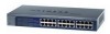
ProSafe 24-port 10/100Mbps Unmanaged Plus Switch JFS524E
Start Here
Estimated Installation Time: 5–10 minutes
Unpack the Box and Verify the Contents
When you open the box, verify that you received everything. The package includes:
•
ProSafe 24-port 10/100Mbps Unmanaged Plus Switch JFS524E
•
AC power cord
•
Rack-mounting screws
•
Installation Guide
(this document)
•
Resource CD
(contains switch configuration software)
If you do not have everything listed above, see the support information card for contact
information. If you are missing the support information card, get contact information at
in the Technical Support section.
Prepare to Install the Switch
Decide where you want to place the switch. Find a flat horizontal surface such as a table,
desk or shelf. The switch comes with rack-mounting screws. You can use the screws if
you want to mount the switch in an equipment rack. Make sure the selected location is:
•
Not in direct sunlight or near a heater or heating vent.
•
Not cluttered or crowded. There should be at least 2 inches (5 cm) of clear space on
all sides of the switch.
•
Well ventilated (especially if it is in a closet).
Also, you will need one Category 5e (Cat 5e) Ethernet cable with RJ-45 connectors for
each device you want to connect to the switch. Each Ethernet cable must be less than 328
feet (100 meters).
Install the Switch and Connect the
Other Devices
1.
Place the switch on a flat surface or mount in a rack.
2.
For each device, insert one end of an Ethernet cable into the port in the device and
insert the other end into one of the Ethernet ports on the switch.
3.
Connect the power cord into the back of the switch and then plug the cord to an AC
power source (such as a wall socket or power strip). The Power light should light up.
4.
Check the LEDs to confirm that all connections are correct.
LED
Activity
Power
•
On
: 24-port Unmanaged Plus Switch has power.
•
Off
: No power.
RJ-45 ports
•
Top LED on/Blink
:
Link/Activity
•
Bottom LED Off/Green
:
10 Mbps/100Mbps.
Power
Reset
Set Up the Switch Configuration Utility
In order to make use of the switch’s enhanced features you can install and use a switch
configuration utility. This utility is on the
Resource CD
shipped with the switch.
Note:
The configuration utility is installed on your PC and is only supported on MS
Windows.
Install the Configuration Utility
To install the Unmanaged Plus Switch Configuration Utility:
1.
Insert the
Resource CD
into a PC connected to the switch.
2.
Click on
Install NETGEAR UM+ Utility
and follow the prompts to install the
program. The switch configuration utility will be installed in the program directory of
your PC and a
NETGEAR UM+ Utility
icon will be placed on your desktop.
Configure the Switch
To configure the switch to use enhanced features:
1.
Double click the
NETGEAR UM+ Utility
icon. The configuration home screen
displays.
2.
The configuration utility displays a list of enhanced switches it discovers on the local
network. Select the switch you want to configure.
3.
You will be asked to enter a password. The default is “password”.
4.
Enter the desired switch configuration. Refer to the
Unmanaged Plus Switch
Configuration Utility User Guide
for a description of enhanced features. The user
guide can be accessed by links on the Help tab of the utility or on the
Resource CD
.
JFS524E_IG_12Aug09.fm
Page 1
Wednesday, August 12, 2009
10:08 AM