Netgear M4300-52G Hardware Installation Guide
Netgear M4300-52G Manual
 |
View all Netgear M4300-52G manuals
Add to My Manuals
Save this manual to your list of manuals |
Netgear M4300-52G manual content summary:
- Netgear M4300-52G | Hardware Installation Guide - Page 1
Hardware Installation Guide M4300 Intelligent Edge Series Fully Managed Stackable Switches January 2020 202-12073-01 NETGEAR, Inc. 350 E. Plumeria Drive San Jose, CA 95134, USA - Netgear M4300-52G | Hardware Installation Guide - Page 2
M4300 Intelligent Edge Series Fully Managed Stackable Switches Support Thank you for purchasing this NETGEAR product. You can visit https://www.netgear.com/support/ to register your product, get help, access the latest downloads and user manuals, and join our community. We recommend that you use - Netgear M4300-52G | Hardware Installation Guide - Page 3
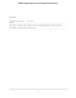
M4300 Intelligent Edge Series Fully Managed Stackable Switches (Continued) Publication Part Publish Date Number Comments 202-11606-02 December 2015 Added information to the Safety Instructions and Warnings section. 202-11606-01 December 2015 First publication. 3 - Netgear M4300-52G | Hardware Installation Guide - Page 4
Hardware features 8 About stacking 10 Safety instructions and warnings 11 Chapter 2 Hardware Overview Hardware descriptions, M4300 series full 10G models 15 Front panel, M4300 series full 10G models 15 Back panel, M4300 series full 10G models 19 LEDs, M4300 series full 10G models 21 Hardware - Netgear M4300-52G | Hardware Installation Guide - Page 5
power supply unit 58 Optional Step 7: Connect a redundant power supply to model M4300-52G-POE 59 Step 8: Check the installation 60 Step 9: Apply AC power Troubleshooting Replace a power supply unit 65 Replace a half-width switch in a rack 66 Troubleshooting chart 68 Additional troubleshooting - Netgear M4300-52G | Hardware Installation Guide - Page 6
edge switches that support non-stop forwarding. In this manual, all models of the M4300 Intelligent Edge Series Fully Managed Stackable Switches are referred to as the switch. Note: All non-modular M4300 switch models are described in this hardware installation guide. NETGEAR provides a separate - Netgear M4300-52G | Hardware Installation Guide - Page 7
-two 10G fiber ports and two 10G RJ45/SFP+ combo ports in a half-width chassis - M4300-48X. Switch model with forty-four copper RJ45 ports and four 10G RJ45/SFP+ combo ports in a full-width chassis - M4300-48XF. Switch model with forty-six 10G fiber ports and two 10G RJ45/SFP+ combo ports in - Netgear M4300-52G | Hardware Installation Guide - Page 8
M4300 Intelligent Edge Series Fully Managed Stackable Switches With these switches, you can create high-speed connections to a server or forty-eight 1000BASE-T PoE+ autosensing ports, two dedicated 10GBASE-T ports, and two dedicated 10GBASE-X SFP+ ports Introduction 8 Hardware Installation Guide - Netgear M4300-52G | Hardware Installation Guide - Page 9
M4300 Intelligent Edge Series Fully Managed Stackable Switches - Full 10G models with combo ports: - Twenty or forty-four independent 10GBASE-T autosensing ports and four 10G RJ45/SFP+ combo ports - Twenty-two or forty-six independent 10G fiber ports and two 10G RJ45/SFP+ combo ports • Support - Netgear M4300-52G | Hardware Installation Guide - Page 10
NETGEAR green power-saving features: - Energy efficiency mode that fully conforms to the IEEE802.3az standard - For 1GBASE-T ports, per-port automatic change to a lower power mode when the port link is down • Support for Power over Ethernet plus (PoE+) on models M4300-16X, M4300-28G-POE+, and M4300 - Netgear M4300-52G | Hardware Installation Guide - Page 11
M4300 Intelligent Edge Series Fully Managed Stackable Switches Switch software is downloaded the software, see the software administration guide and user manual, which you can download by visiting netgear.com/support/download/. Safety instructions and warnings Use the following safety guidelines - Netgear M4300-52G | Hardware Installation Guide - Page 12
system components, and never operate the product in a wet environment. If the system gets wet, see the appropriate section in your troubleshooting guide, or contact your trained service provider. • Do not push any objects into the openings of your system. Doing so can cause fire or electric shock by - Netgear M4300-52G | Hardware Installation Guide - Page 13
M4300 Intelligent Edge Series Fully Managed Stackable a power adapter: - If you were not provided with a power adapter, contact your local NETGEAR reseller. - The power adapter must be rated for the product and for the voltage and national wiring rules. Introduction 13 Hardware Installation Guide - Netgear M4300-52G | Hardware Installation Guide - Page 14
switch hardware features. The chapter includes the following sections: • Hardware descriptions, M4300 series full 10G models • Hardware descriptions, M4300 series 1G models with 10G uplinks • Hardware descriptions, M4300 series full 10G models with RJ45/SFP+ combo ports • Switch hardware interfaces - Netgear M4300-52G | Hardware Installation Guide - Page 15
-16X The following figure illustrates the front panel of half-width model M4300-16X. Figure 1. Front panel model M4300-16X Number 1 2 3 4 5 Description Power, PoE Max, and Fan LEDs Stack ID LED USB port RJ-45 RS232 console port Stack Master LED Hardware Overview 15 Hardware Installation Guide - Netgear M4300-52G | Hardware Installation Guide - Page 16
. The right port LED indicates the PoE status. Model M4300-8X8F The following figure illustrates the front panel of half-width model M4300-8X8F. Figure 2. Front panel model M4300-8X8F Number 1 2 3 4 5 6 7 8 10GBASE-T ports, each with a port LED Hardware Overview 16 Hardware Installation Guide - Netgear M4300-52G | Hardware Installation Guide - Page 17
12X12F The following figure illustrates the front panel of half-width model M4300-12X12F. Figure 3. Front panel model M4300-12X12F Number 1 2 3 4 5 6 7 8 Description Power and -T ports, each with a port LED Model M4300-24X24F The following figure illustrates the front panel of full-width model - Netgear M4300-52G | Hardware Installation Guide - Page 18
M4300 series full 10G models on page 21) . Because model M4300-24X24F can support M4300-16X, M4300-8X8F, and M4300-24X24F). On model M4300-12X12F, the RJ-45 RS232 console port is on the back panel. • One out-of-band (OOB) 1G Ethernet port (models M4300-16X, M4300-8X8F, and M4300 LEDs, M4300 series - Netgear M4300-52G | Hardware Installation Guide - Page 19
model M4300-16X. Figure 5. Back panel model M4300-16X Number 1 Description PSU with AC connector From left to right, the back panel of model M4300-16X . Model M4300-8X8F The following figure illustrates the back panel of half-width model M4300-8X8F. Figure 6. Back panel model M4300-8X8F Number - Netgear M4300-52G | Hardware Installation Guide - Page 20
Model M4300-12X12F The following figure illustrates the back panel of half-width model M4300-12X12F. Figure 7. Back panel model M4300-12X12F LEDs PSU with AC connector From left to right, the back panel of model M4300-12X12F provides the following components: • One out-of-band 1G Ethernet port. - Netgear M4300-52G | Hardware Installation Guide - Page 21
is not supplied to the switch. Note: Because model M4300-24X24F can support two PSUs, the front panel provides both a Power 1 LED and Power 2 LED. PoE model (M4300-16X) PoE Max LED Off. Sufficient (more than 7W switch is not a member of a stack. Hardware Overview 21 Hardware Installation Guide - Netgear M4300-52G | Hardware Installation Guide - Page 22
PoE current exceeds the PD's classification. • An out-of-proper-voltage band condition occurred. PoE model (M4300-16X), left side speed, activity, and link LED: Off. No link is established on the copper port 5 Gbps, 2.5 Gbps, 1 Gbps, or 100 Mbps. Hardware Overview 22 Hardware Installation Guide - Netgear M4300-52G | Hardware Installation Guide - Page 23
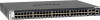
M4300-28G. Switch model with twenty-four 1G copper ports, two 10G copper ports, and two 10G fiber ports • M4300 M4300-52G. Switch model with forty-eight 1G copper ports, two 10G copper ports, and two 10G fiber ports • M4300 , M4300 series M4300-28G. Model M4300-28G Figure 9. Front panel model M4300 - Netgear M4300-52G | Hardware Installation Guide - Page 24
with a port LED 10GBASE-X SFP+ ports, each with a port LED USB port Model M4300-28G-POE+ Model M4300-28G-POE+ supports PoE+ on ports 1 through 24. The following figure illustrates the front panel of full-width + ports, each with a port LED USB port Hardware Overview 24 Hardware Installation Guide - Netgear M4300-52G | Hardware Installation Guide - Page 25
The following figure illustrates the front panel of full-width model M4300-52G. Figure 11. Front panel model M4300-52G Number 1 2 3 4 5 6 7 8 9 10 + ports, each with a port LED USB port Model M4300-52G-POE+ Model M4300-52G-POE+ supports PoE+ on ports 1 through 48. The following figure illustrates - Netgear M4300-52G | Hardware Installation Guide - Page 26
and system LEDs (see LEDs, M4300 series 1G models with 10G uplinks M4300 series 1G models with 10G uplinks M4300-28G-POE+ and model M4300 M4300 series 1G models with 10G uplinks on page 29): - On model M4300-28 and model M4300-28G-POE+, these are port numbers 25 and 26. - On model M4300-52G and model M4300 - Netgear M4300-52G | Hardware Installation Guide - Page 27
, M4300 series 1G models with M4300-28G, M4300-28G-POE+, and M4300-52G The following figure illustrates the back panel of full-width models M4300-28G, M4300-28G-POE+, and M4300-52G. Figure 13. Back panel models M4300-28G, M4300-28G-POE+, and M4300 models M4300-28G, M4300-28G-POE+, and M4300-52G - Netgear M4300-52G | Hardware Installation Guide - Page 28
console port RPS interface PSU1 with AC connector Bay for PSU2 From left to right, the back panel of model M4300-52G-POE+ provides the following components: • One RJ-45 RS232 (115200, N, 8, 1) console port. • modular bay for an optional second PSU. Hardware Overview 28 Hardware Installation Guide - Netgear M4300-52G | Hardware Installation Guide - Page 29
Intelligent Edge Series Fully Managed Stackable Switches LEDs, M4300 series 1G models with 10G uplinks This section describes the LED designations of the 1G models with a link. Blinking green. The copper port is transmitting or receiving packets. Hardware Overview 29 Hardware Installation Guide - Netgear M4300-52G | Hardware Installation Guide - Page 30
M4300 Intelligent Edge Series Fully Managed Stackable Switches Table 2. LEDs of the 1G models with 10G uplinks (Continued) LED Description PoE green. The port is transmitting or receiving packets. Off. No link is established on the port. Hardware Overview 30 Hardware Installation Guide - Netgear M4300-52G | Hardware Installation Guide - Page 31
width chassis • M4300-48X. Switch model with forty-four copper RJ45 ports and four 10G RJ45/SFP+ combo ports in a full-width chassis • M4300-48XF. Switch model with Model M4300-24X The following figure illustrates the front panel of half-width model M4300-24X. Figure 15. Front panel model M4300-24X - Netgear M4300-52G | Hardware Installation Guide - Page 32
-X SFP+ combo ports are on the back panel) Model M4300-24XF The following figure illustrates the front panel of half-width model M4300-24XF. Figure 16. Front panel model M4300-24XF Number 1 2 3 4 5 6 7 8 Figure combo ports are on the back panel) Hardware Overview 32 Hardware Installation Guide - Netgear M4300-52G | Hardware Installation Guide - Page 33
port LED: Ports 45T, 46T, 47T, and 48T are 10GBASE-T ports Ports 45F, 46F, 47F, and 48F 10GBASE-X SFP+ ports Model M4300-48XF The following figure illustrates the front panel of full-width model M4300-48XF. Figure 18. Front panel model M4300-48XF Hardware Overview 33 Hardware Installation Guide - Netgear M4300-52G | Hardware Installation Guide - Page 34
(see LEDs, M4300X series full 10G models with RJ45/SFP+ combo ports on page 38). Because models M4300-48X and M4300-48XF can support two PSUs, the front panel provides both a Power 1 LED and Power 2 LED. • Recessed Reset + combo ports on page 38). Hardware Overview 34 Hardware Installation Guide - Netgear M4300-52G | Hardware Installation Guide - Page 35
combo ports are on the front panel) PSU with AC connector From left to right, the back panel of model M4300-24X provides the following components: • Fixed fan for front-to-back air flow • One RJ-45 RS232 (115200, supply unit (PSU) is installed. Hardware Overview 35 Hardware Installation Guide - Netgear M4300-52G | Hardware Installation Guide - Page 36
combo ports are on the front panel) PSU with AC connector From left to right, the back panel of model M4300-24XF provides the following components: • Fixed fan for front-to-back air flow. • One RJ-45 RS232 (115200, supply unit (PSU) is installed. Hardware Overview 36 Hardware Installation Guide - Netgear M4300-52G | Hardware Installation Guide - Page 37
AC connector OOB port with port LEDs Bay for PSU 2 From left to right, the back panel of model M4300-48X provides the following components: • Modular bay for power supply unit 1 (PSU 1), which is an APS250W. • Fixed 2 for an optional second PSU. Hardware Overview 37 Hardware Installation Guide - Netgear M4300-52G | Hardware Installation Guide - Page 38
M4300-48XF The following figure illustrates the back panel of full-width model M4300-48XF. Figure 22. Back panel model M4300-48XF , the back panel of model M4300-48XF provides the following components: • M4300-24X, the LEDs for the 10GBASE-X SFP+ combo ports are on the back panel. • For model M4300 - Netgear M4300-52G | Hardware Installation Guide - Page 39
M4300 to the switch. Note: Because models M4300-48X and M4300-48XF can support two PSUs, the front panel provides packets at 1 Gbps or 100 Mbps. Note: On model M4300-24XF, the 10GBASE-T RJ45 combo ports are on the back . Note: On model M4300-24X, the 10GBASE-X SFP+ combo ports are - Netgear M4300-52G | Hardware Installation Guide - Page 40
M4300 series switch models. Cables and speed The following table describes the network cables that you can use for the switch connections and the speeds that these cables can support copper RJ-45 ports support autosensing. When you insert attached device. All ports support a Category 5 (Cat support - Netgear M4300-52G | Hardware Installation Guide - Page 41
M4300-28G supports half-duplex mode on ports 1 to 16 only. • Model M4300-28G-POE+ supports half-duplex mode on ports 1 to 16 only. • Model M4300-52G supports ), all of which are sold separately. The switch supports the following NETGEAR SFP and SFP+ transceiver modules and cables: • Installation Guide - Netgear M4300-52G | Hardware Installation Guide - Page 42
-T, SFP+ copper RJ-45 GBIC Note: The AXM765 module is supported on switch models M4300-24XF and M4300-48XF only. • Direct attach cables: - AXC761. SFP+ 1m direct For more information about NETGEAR SFP and SFP+ transceiver modules and cables, visit netgear.com/business/products/switches/modules - Netgear M4300-52G | Hardware Installation Guide - Page 43
terminal emulation software and Windows USB driver, visit https://www.netgear.com/support/, enter your model number in the search box, and click RPS) interface on model M4300-52G-POE+ provides a receptacle for an RPS cable such as the NETGEAR DC Connection Cable Model Hardware Installation Guide - Netgear M4300-52G | Hardware Installation Guide - Page 44
two PSUs, you can order a second PSU as an option. Table 5. Supported PSUs Switch Model M4300-16X M4300-8X8F M4300-12X12F M4300-24X24F M4300-28G M4300-52G M4300-28G-POE+ M4300-52G-POE+ M4300-24X M4300-24XF Possible PSU Configurations Power Redundancy 1x APS299W 1x APS600W 1x APS250W 1x - Netgear M4300-52G | Hardware Installation Guide - Page 45
Supported PSUs (Continued) Switch Model M4300-48X M4300-48XF Possible PSU Configurations 1x APS250W 2x APS250W 1x APS250W 2x APS250W Power Redundancy RPS Support Note: For models M4300-28G-POE+ and M4300 630W 591W 220 VAC input 720W 860W Hardware Overview 45 Hardware Installation Guide - Netgear M4300-52G | Hardware Installation Guide - Page 46
Managed Stackable Switches Table 7. PSUs and PoE budgets models M4300-28G-POE+ and M4300-52G-POE+ (Continued) PSU PSU Configuration (Single or VAC input EPS mode, 110 VAC input EPS mode, 220 VAC input M4300-28G-POE+ M4300-52G-POE+ PoE Power Budget PoE Power Budget 630W 591W 720W 860W 720W - Netgear M4300-52G | Hardware Installation Guide - Page 47
• Optional Step 5: Install SFP transceiver modules • Optional Step 6: Install a power supply unit • Optional Step 7: Connect a redundant power supply to model M4300-52G-POE+ • Step 8: Check the installation • Step 9: Apply AC power and check the LEDs • Optional Step 10: Connect a console to the - Netgear M4300-52G | Hardware Installation Guide - Page 48
M4300 Intelligent Edge Series Fully Managed Stackable Switches Step 1: Prepare the site Before you install the switch, make sure that the operating as the microprocessor. You can do so by periodically touching an unpainted metal surface on the switch. Installation 48 Hardware Installation Guide - Netgear M4300-52G | Hardware Installation Guide - Page 49
23. Switch package contents, half-width models The following figure shows full-width model M4300-52G. The package contents for the other full-width models (M4300-24X24F, M4300-28G, M4300-28G-POE+, M4300-52G-POE+, M4300-48X, and M4300-48XF) are the same. Installation 49 Hardware Installation Guide - Netgear M4300-52G | Hardware Installation Guide - Page 50
M4300 Intelligent Edge Series Fully Managed Stackable Switches Figure 24. Switch package contents, full-width models Check the contents of the boxes to make sure that all items are present before installing the switch. If any item is missing or damaged, contact your local NETGEAR reseller for - Netgear M4300-52G | Hardware Installation Guide - Page 51
-width switch (models M4300-16X, M4300-8X8F, M4300-12X12F, or M4300-24X) in a single rack space. You can also install two half-width switches (models M4300-16X, M4300-8X8F, M4300-12X12F, M4300-24X, or a to secure mounting brackets to the rack. Installation 51 Hardware Installation Guide - Netgear M4300-52G | Hardware Installation Guide - Page 52
Edge Series Fully Managed Stackable Switches The following figure shows model M4300-52G-POE+. However, you install the other full-width models The figures in the following procedure shows model M4300-24X. However, you install the other half-width models in the same manner. Installation - Netgear M4300-52G | Hardware Installation Guide - Page 53
M4300 Intelligent Edge Series Fully Managed Stackable Switches To install a single half-width switch in a single rack space: 1. Attach the supplied rack. 5. Tighten the screws with a No. 2 Phillips screwdriver to secure mounting brackets to the rack. Installation 53 Hardware Installation Guide - Netgear M4300-52G | Hardware Installation Guide - Page 54
half-width models in the same manner. For example, you can also install two M4300-8X8F switches or one M4300-8X8F switch and one M4300-12X12F switch in a single rack space. To install two single half-width switches mount to the right side of the switch. Installation 54 Hardware Installation Guide - Netgear M4300-52G | Hardware Installation Guide - Page 55
M4300 Intelligent Edge Series Fully Managed Stackable Switches 3. Slide the inside middle mounts on the left switch into the outside middle mounts in each middle mount. 5. Tighten the screws with a No. 1 Phillips screwdriver to secure each middle mount. Installation 55 Hardware Installation Guide - Netgear M4300-52G | Hardware Installation Guide - Page 56
information about supported modules, see 10GBASE-X, 1000BASE-X, and 1000BASE-T transceiver modules and cables for SFP+ ports on page 41. Note: Contact your NETGEAR sales office for model M4300-16X, M4300-8X8F, model M4300-12X12F, and model M4300-24X24F. Installation 56 Hardware Installation Guide - Netgear M4300-52G | Hardware Installation Guide - Page 57
ports. That is, this procedure is for models M4300-24X, M4300-24XF, M4300-28G, M4300-28G-POE+, M4300-48X, M4300-48FX, M4300-52G, and M4300-52G-POE+. For models M4300-24X and M4300-24XF, the SFP+ combo ports are on seat it securely into the connector. Installation 57 Hardware Installation Guide - Netgear M4300-52G | Hardware Installation Guide - Page 58
following full-width models provide a second power module bay in which you can install an optional second PSU: • M4300-24X24F, M4300-48X, and M4300-48XF • M4300-28G and M4300-28G-POE+ • M4300-52G and M4300-52G-POE+ For these models, the PSU that is shipped with the product is installed in the power - Netgear M4300-52G | Hardware Installation Guide - Page 59
the connectors on the rear of the PSU and on the midplane. The following figure shows model M4300-24X24F. However, you install a second PSU in models M4300-28G, M4300-28G-POE+, M4300-48X, M4300-48XF, M4300-52G, and M4300-52G-POE+ in the same manner. 3. Connect the end of the power cord to the power - Netgear M4300-52G | Hardware Installation Guide - Page 60
M4300 Intelligent Edge Series Fully Managed Stackable Switches To install the RPS and apply power: 1. Power off the switch. 2. Loosen the are not damaged or creating a safety hazard. 4. Make sure that all equipment is mounted properly and securely. Installation 60 Hardware Installation Guide - Netgear M4300-52G | Hardware Installation Guide - Page 61
as expected. For more information about the LEDs, see the following sections: • LEDs, M4300 series full 10G models on page 21 • LEDs, M4300 series 1G models with 10G uplinks on page 29 • LEDs, M4300X series full 10G models that the power source is good. Installation 61 Hardware Installation Guide - Netgear M4300-52G | Hardware Installation Guide - Page 62
port is located on the front panel. • On the full-width models (M4300-24X24F, M4300-28G, M4300-28G-POE+, M4300-48X, M4300-48XF, M4300-52G, and M4300-52G-POE+), the RJ-45 RS232 console port is located on the back panel rate. 115,200 bps • Data bits. 8 Installation 62 Hardware Installation Guide - Netgear M4300-52G | Hardware Installation Guide - Page 63
which you can download by visiting netgear.com/support/download/. For information about configuring the switch through its local browser interface, see the software administration guide and the user manual, which you can download by visiting netgear.com/support/download/. Installation 63 Hardware - Netgear M4300-52G | Hardware Installation Guide - Page 64
4 Maintenance and Troubleshooting This chapter provides information about maintaining and troubleshooting the switch. The chapter includes the following sections: • Replace a power supply unit • Replace a half-width switch in a rack • Troubleshooting chart • Additional troubleshooting suggestions 64 - Netgear M4300-52G | Hardware Installation Guide - Page 65
the switch remains powered on and functioning. The figures in the following procedure show models M4300-24X24F and M4300-24X. To remove one PSU and reinstall another PSU in the same power module bay: the bay until the latch locks. Maintenance and Troubleshooting 65 Hardware Installation Guide - Netgear M4300-52G | Hardware Installation Guide - Page 66
M4300 support beneath the half-width switches when removing or installing a half-width switch. The support keeps the switches level while the mounting screws are loosened to avoid damage to both the switch and the middle mount screws. Maintenance and Troubleshooting 66 Hardware Installation Guide - Netgear M4300-52G | Hardware Installation Guide - Page 67
M4300 Intelligent Edge Series Fully want to replace. 2. Insert an item under the two half-width switches that can support the switches and keep them level during removal and installation. 3. Loosen the screws with LEDs on page 61). Maintenance and Troubleshooting 67 Hardware Installation Guide - Netgear M4300-52G | Hardware Installation Guide - Page 68
M4300 Intelligent Edge Series Fully Managed Stackable Switches Troubleshooting chart The following table lists symptoms, causes, and solutions for possible problems. Table 9. Troubleshooting chart links used as the stacking ports. Maintenance and Troubleshooting 68 Hardware Installation Guide - Netgear M4300-52G | Hardware Installation Guide - Page 69
disconnect the AC power from the switch and then reconnect the AC power. If the problem continues, contact NETGEAR Technical Support. For more information, visit the support website at support.netgear.com. • Autonegotiation. The RJ-45 ports negotiate the correct duplex mode, speed, and flow control
-
 1
1 -
 2
2 -
 3
3 -
 4
4 -
 5
5 -
 6
6 -
 7
7 -
8
-
9
-
10
-
11
-
12
-
13
-
14
-
15
-
16
-
17
-
18
-
19
-
20
-
21
-
22
-
23
-
24
-
25
-
26
-
27
-
28
-
29
-
30
-
31
-
32
-
33
-
34
-
35
-
36
-
37
-
38
-
39
-
40
-
41
-
42
-
43
-
44
-
45
-
46
-
47
-
48
-
49
-
50
-
51
-
52
-
53
-
54
-
55
-
56
-
57
-
58
-
59
-
60
-
61
-
62
-
63
-
64
-
65
-
66
-
67
-
68
-
69
 |
 |

Hardware Installation Guide
M4300 Intelligent Edge Series
Fully Managed Stackable Switches
NETGEAR, Inc.
350 E. Plumeria Drive
January 2020
San Jose, CA 95134, USA
202-12073-01