Netgear M5300-28G3 Hardware Installation Guide
Netgear M5300-28G3 Manual
 |
View all Netgear M5300-28G3 manuals
Add to My Manuals
Save this manual to your list of manuals |
Netgear M5300-28G3 manual content summary:
- Netgear M5300-28G3 | Hardware Installation Guide - Page 1
Managed Stackable Switch M5300 Series Hardware Installation Guide 350 East Plumeria Drive San Jose, CA 95134 USA December 2012 202-11104-02 - Netgear M5300-28G3 | Hardware Installation Guide - Page 2
NETGEAR Managed Stackable Switch M5300 Series © All rights reserved No part of this publication may be reproduced, transmitted, transcribed, stored in a retrieval system, or translated into any language in any form or by any means without the written permission of NETGEAR, Inc. NETGEAR, the NETGEAR - Netgear M5300-28G3 | Hardware Installation Guide - Page 3
RJ-45 Ports 19 Connect a Console to the Switch 20 Chapter 3 Troubleshooting Troubleshooting Chart 22 Additional Troubleshooting Suggestions 23 Appendix A Technical Specifications Specifications for M5300 Series 24 Appendix B Default Configuration Settings Appendix C Notification of Compliance - Netgear M5300-28G3 | Hardware Installation Guide - Page 4
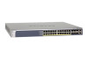
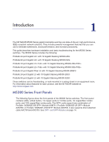
M5300-28G-POE+ ProSafe 48-port Gigabit L2+ PoE+ with 10 Gigabit Stacking M5300-52G-POE+ ProSafe 24-port Gigabit Fiber L3 with 10 Gigabit Stacking M5300-28GF3 ProSafe 24-port Gigabit L3 with 10 Gigabit Stacking M5300-28G3 ProSafe 48-port Gigabit L3 with 10 Gigabit Stacking M5300-52G3 These switches - Netgear M5300-28G3 | Hardware Installation Guide - Page 5
NETGEAR Managed Stackable Switch M5300 Series LEDs Reset button Figure 1. Typical series front panel Copper ports 1G combo ports 10G combo ports Introduction 5 - Netgear M5300-28G3 | Hardware Installation Guide - Page 6
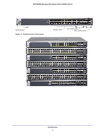
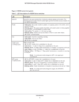
NETGEAR Managed Stackable Switch M5300 Series Figure 2. M5300 series front panels Table 1. LED descriptions for M5300 Series switches LED Stack ID Power Fan 10GBT ports (1 LED per port) SFP+ ports (1 LED per port) Description Stack ID is the stack member ID (1-8) that the software assigns to the - Netgear M5300-28G3 | Hardware Installation Guide - Page 7
NETGEAR Managed Stackable Switch M5300 Series Table 1. LED descriptions for M5300 Series switches (continued) LED support any combination of: • ProSafe 10 Gigabit Ethernet XFP Adapter (AX741) • ProSafe 24 Gigabit Stackable Module (AX742) • ProSafe 10 Gigabit Ethernet SFP+ Adapter (AX743) • ProSafe - Netgear M5300-28G3 | Hardware Installation Guide - Page 8
NETGEAR Managed Stackable Switch M5300 Series Safety Instructions Use the following safety guidelines to environment. If the system gets wet, see the appropriate section in your troubleshooting guide, or contact your trained service provider. • Do not push any objects into the openings of your system - Netgear M5300-28G3 | Hardware Installation Guide - Page 9
NETGEAR Managed Stackable Switch M5300 Series cable approved for your country. The power cable must be rated for the product and for the voltage and current marked on the product - Netgear M5300-28G3 | Hardware Installation Guide - Page 10
The CD either includes these documents or links to access them: - Managed Switch CLI Manual, Version 10.0 - Managed Switch Administration Guide - Managed Switch Installation Guide - This hardware installation guide Protect Against Electrostatic Discharge WARNING: Static electricity can harm delicate - Netgear M5300-28G3 | Hardware Installation Guide - Page 11
NETGEAR Managed Stackable Switch M5300 Series You can also take the following steps to prevent damage from Contents on page 10 Note: If any item is missing or damaged, contact your local NETGEAR reseller for replacement. 5. Inspect the products and accessories for damage. Report any damage - Netgear M5300-28G3 | Hardware Installation Guide - Page 12
NETGEAR Managed Stackable Switch M5300 Series Note: The thumbscrews on the rear modules must be tightened with a tool after both initial installation and subsequent access to the modules. Select a Location The switch can be mounted in a standard 19-inch (48.26-centimeter) rack, wall-mounted, or - Netgear M5300-28G3 | Hardware Installation Guide - Page 13
NETGEAR Managed Stackable Switch M5300 Series Install the Switch You can install the switch on a flat surface or in a standard 19-inch rack. Install the Switch on a Flat Surface The switch ships with four self-adhesive rubber footpads. Stick one rubber footpad on each of the four concave spaces on - Netgear M5300-28G3 | Hardware Installation Guide - Page 14
NETGEAR Managed Stackable Switch M5300 Series Check the Installation Before you apply power, perform the For help with troubleshooting, see Chapter 3,Troubleshooting on page 22." SFP+ and SFP Modules SFP+ and SFP modules (sold separately) can be inserted directly into the switch ports. Figure 4. - Netgear M5300-28G3 | Hardware Installation Guide - Page 15
NETGEAR Managed Stackable Switch M5300 Series • AXM761: SFP+ module with an LC connector that is compatible with the IEEE SFP+ or SFP modules: 1. Insert the SFP+ or SFP module into the switch port. 2. Press firmly to ensure that the module seats into the connector. Tx Rx Hardware Installation 15 - Netgear M5300-28G3 | Hardware Installation Guide - Page 16
NETGEAR Managed Stackable Switch M5300 Series Create a Stack You can connect up to eight switches to form a stack with a single management IP address. The switches automatically select a master unit. Once the master is selected, you can use its console to manage all the switches in the stack. You - Netgear M5300-28G3 | Hardware Installation Guide - Page 17
with the CLI, see the Command Line Interface manual on the resource CD that shipped with your product. Stacking Using IO Module on the Rear Panel You can connect up to eight switches to form a stack with a single management IP address. The switches automatically select a master unit. Once the master - Netgear M5300-28G3 | Hardware Installation Guide - Page 18
NETGEAR Managed Stackable Switch M5300 Series For information about working with the CLI, see the Command Line Interface Reference for the ProSafe M5300 Series Stackable Switches on the Resource CD that shipped with your product. Power Module Bay The power module bay provides an easy way to replace - Netgear M5300-28G3 | Hardware Installation Guide - Page 19
NETGEAR Managed Stackable Switch M5300 Series 3. Loosen the two captive screws on the power module. 4. Remove the power module from the power module slot by pulling on the extraction handle. Connect a Redundant Power Supply Each switch has a redundant power supply (RPS) connector at the rear of the - Netgear M5300-28G3 | Hardware Installation Guide - Page 20
NETGEAR Managed Stackable Switch M5300 Series Connect a Console to the Switch After you install the switch and apply power, you can connect to it with a terminal or workstation. You can use the command-line interface (CLI) to identify the IP address. To use a console, you need the following items: - Netgear M5300-28G3 | Hardware Installation Guide - Page 21
NETGEAR Managed Stackable Switch M5300 Series After you connect a console to the switch, you will need to configure it. The following documents are provided for this purpose: • Installation guide: Explains basic setup and configuration (provided as both a print document and in PDF format on the - Netgear M5300-28G3 | Hardware Installation Guide - Page 22
, and solutions of possible problems. Table 3. Troubleshooting chart Problem Cause Solution Power LED is off. No power is received. Link LED is off or intermittent. Port connection is not working. Check the power cord connections for the switch at the switch and the connected device. Make - Netgear M5300-28G3 | Hardware Installation Guide - Page 23
NETGEAR Managed Stackable Switch M5300 Series Additional Troubleshooting Suggestions If the suggestions in Table 3 on page 22 do not solve your problem, refer to the troubleshooting suggestions in this section. • Network adapter cards Make sure that the network adapter cards installed in the PCs are - Netgear M5300-28G3 | Hardware Installation Guide - Page 24
specifications Feature IEEE Network Protocol and Standards compatibility Layer 2 services M5300 • 802.3i 10BASE-T • 802.3u 100BASE-TX Spanning Tree Protocol (MSTP) • 802.3ad Link Aggregation (LACP) • IGMP v1, v2 Snooping Support • DHCP L2 Relay • UDP Relay • SNTP • SNMP v1/v2/v3 • LLDP/LLDP-MED - Netgear M5300-28G3 | Hardware Installation Guide - Page 25
NETGEAR Managed Stackable Switch M5300 Series Table 4. M5300 Series technical specifications (continued) Switch management Telnet sessions for management CPU (5) • Ping support • ARP support • Private IP Source Guard • Dynamic ARP Inspection • Captive Portal • MAC ACL (inbound/outbound) • IP - Netgear M5300-28G3 | Hardware Installation Guide - Page 26
NETGEAR Managed Stackable Switch M5300 Series Table 4. M5300 Series technical specifications (continued) System Service Stacking Addressing MAC Address entries Performance Interface • DHCP, BOOTP Relay • DHCP Server • Maximum of 8 switches in a single stack • RING Topology support • CHAIN - Netgear M5300-28G3 | Hardware Installation Guide - Page 27
NETGEAR Managed Stackable Switch M5300 Series Table 4. M5300 Series technical specifications (continued) Bandwidth • 136 Gbps (M5300-28G3/M5300-28G/M5300-28GF3/M5300-28G-POE+) • 184 Gbps (M5300-52G3/M5300-52G/M5300-52G-POE+) Dimensions (W x D x H) 440 x 391 x 43 mm (17.3 x 15.4 x 1.7 in.) - Netgear M5300-28G3 | Hardware Installation Guide - Page 28
NETGEAR Managed Stackable Switch M5300 Series Table 5. Technical specifications - model specific Feature M5300-28G-POE+ M5300-52G-POE+ M5300-28G M5300-52G M5300-28G3 M5300-52G3 M5300-28GF3 Maximum power consumption M5300-28G-PoE+: 535W M5300-52G-PoE+: 556W M5300-28G: 55W M5300-52G:79W M5300- - Netgear M5300-28G3 | Hardware Installation Guide - Page 29
Enabled Gigabit port type Auto detect Management IP configuration DHCP Password protection Disabled User name Admin Password (none) Web access Enabled Java mode Enabled VLAN All ports belong to default VLAN (VLAN 1) as untagged ports IP multicast filtering Disabled Spanning Tree - Netgear M5300-28G3 | Hardware Installation Guide - Page 30
NETGEAR Managed Stackable Switch M5300 Series Table 6. Default settings Feature GMRP IP routing MAC address aging SNMP community DHCP server VLAN ingress filtering IP multicast filtering 802.1x Port security Captive portal Auto install LLDP LLDP-MED ISDP Default Setting Disabled Disabled 300 - Netgear M5300-28G3 | Hardware Installation Guide - Page 31
certain restrictions. Please refer to the notes in the operating instructions. Federal Office for Telecommunications Approvals has been notified of the Communications Radio Interference Regulations This digital apparatus (NETGEAR M5300 Managed Stackable Switches) does not exceed the Class A limits - Netgear M5300-28G3 | Hardware Installation Guide - Page 32
the application of EN 55024 Class A (CISPR 22). EN 55 022 and EN 55 024 Statements This is to certify that the NETGEAR M5300 Managed Stackable Switches are shielded against the generation of radio interference in accordance with the application of Council Directive 89/336/EEC, Article 4a. Conformity
-
 1
1 -
 2
2 -
 3
3 -
 4
4 -
 5
5 -
 6
6 -
 7
7 -
8
-
9
-
10
-
11
-
12
-
13
-
14
-
15
-
16
-
17
-
18
-
19
-
20
-
21
-
22
-
23
-
24
-
25
-
26
-
27
-
28
-
29
-
30
-
31
-
32
 |
 |

350 East Plumeria Drive
San Jose, CA 95134
USA
December 2012
202-11104-02
Managed Stackable Switch
M5300 Series
Hardware Installation Guide