Netgear SW510 Installation Guide
Netgear SW510 - Switch Manual
 |
UPC - 606449000955
View all Netgear SW510 manuals
Add to My Manuals
Save this manual to your list of manuals |
Netgear SW510 manual content summary:
- Netgear SW510 | Installation Guide - Page 1
Installation Guide for the Model SW510 and Model SW518 Ethernet Switches NETGEAR, Inc. 4500 Great America Parkway Santa Clara, CA 95054 USA Phone: 1-888-NETGEAR E-mail: [email protected] www.NETGEAR.com M-SW510NA-1 September 2000 - Netgear SW510 | Installation Guide - Page 2
not installed and used in accordance with the instruction manual, it may cause harmful interference to radio user may be required to take appropriate measures. Bestätigung des Herstellers/Importeurs Es wird hiermit bestätigt, daß das NETGEAR Model SW510 and Model SW518 Ethernet Switches - Netgear SW510 | Installation Guide - Page 3
such as radios and TV receivers. Customer Support For assistance with installing and configuring your NETGEAR system or with post-installation questions or problems, contact your point of purchase representative. To contact customer support or to purchase additional copies of this document - Netgear SW510 | Installation Guide - Page 4
iv - Netgear SW510 | Installation Guide - Page 5
1-1 Features ...1-2 Chapter 2 Physical Description Front Panel ...2-1 Ethernet Ports ...2-2 Normal/Uplink Push Button 2-3 LEDs ...2-4 Rear Panel ...2-5 HDX/FDX/AUTO Duplex Toggle Switches 2-6 Chapter 3 Applications Desktop Switching ...3-1 Network Segmentation 3-2 Bridging from 10 Mbps to 100 - Netgear SW510 | Installation Guide - Page 6
Chapter 5 Troubleshooting LEDs ...5-1 HDX/FDX/AUTO Duplex Toggle Switches 5-1 Installation ...5-2 Cabling ...5-2 Network Adapter Cards 5-2 Configuration ...5-2 Switch Integrity ...5-2 Appendix A Technical Specifications General Specifications A-1 Appendix B Connector Pin Assignments RJ-45 Plug and - Netgear SW510 | Installation Guide - Page 7
vista RJ-45 connector with built-in LEDs 2-3 Rear panel of the Model SW510 switch 2-5 Rear panel of the Model SW518 switch 2-5 Model SW510 switch used as a desktop switch 3-2 Model SW518 switches used for network segmentation and as a multiport bridge to a high-bandwidth backbone 3-3 Bridging - Netgear SW510 | Installation Guide - Page 8
Tables Table 2-1. LED descriptions 2-4 Table B-1. Pin assignments for the RJ-45 plug and vista RJ-45 connector B-2 Table C-1. Electrical requirements of Category 3, 4, and 5 cables C-2 viii Tables - Netgear SW510 | Installation Guide - Page 9
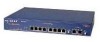
Congratulations on your purchase of the NETGEAR Model SW510 10-port 10/100 Mbps Ethernet Switch or the NETGEAR Model SW518 18-port 10/100 Mbps Ethernet Switch. These switches are part of the NETGEAR™ 500-series product family. The switches allow simultaneous transmission of multiple packets - Netgear SW510 | Installation Guide - Page 10
Installation Guide for the Model SW510 and Model SW518 Ethernet Switches Increased bandwidth is another advantage of the Model SW510 and Model SW518 switches. In addition to 10 Mbps ports, each switch has two Fast Ethernet ports that create a high-throughput connection to a backbone or server with - Netgear SW510 | Installation Guide - Page 11
Installation Guide for the Model SW510 and Model SW518 Ethernet Switches • Two 10/100 Mbps ports on each of the switches One of the 10/100 Mbps ports is configurable as Normal (MDI-X) or Uplink (MDI). • Switch-selectable half/full-duplex mode for the 10 Mbps ports In full-duplex mode, the throughput - Netgear SW510 | Installation Guide - Page 12
- Netgear SW510 | Installation Guide - Page 13
Chapter 2 Physical Description This chapter explains the hardware features of the NETGEAR Model SW510 and Model SW518 Ethernet switches. It is divided into sections explaining the front and rear panels of the switches. Use the key at the bottom of each illustration to identify the panel components. - Netgear SW510 | Installation Guide - Page 14
Installation Guide for the Model SW510 and Model SW518 Ethernet Switches 1 2 3 4 5 6 7 18 PORT 10/100Mbps Ethernet Switch 1234 56 7 8 100 Mbps 1 Link FDX Power 9 10 11 12 13 14 15 16 17 18 Green = Rx/Tx Yellow = Collision 9 10/100 Mbps MODELSW518 - Netgear SW510 | Installation Guide - Page 15
Guide for the Model SW510 and Model SW518 Ethernet Switches Each of the 10 Mbps and 10/100 Mbps ports uses vista RJ-45 connectors that have built-in LEDs, as illustrated in Figure 2-3. The LEDs, as described in Table 2-1, indicate that the connection to the port is valid and that the port - Netgear SW510 | Installation Guide - Page 16
Installation Guide for the Model SW510 and Model SW518 Ethernet Switches LEDs The LEDs on the Model SW510 and the Model SW518 switches are used to monitor and diagnose the devices. LEDs on the front panel of the switch and two LEDs on each port allow you to identify the following information: • - Netgear SW510 | Installation Guide - Page 17
Installation Guide for the Model SW510 and Model SW518 Ethernet Switches Rear Panel As illustrated in Figure 2-4 and Figure 2-5, the rear panel has full-duplex (FDX), half-duplex (HDX), and auto-duplex (AUTO) toggle switches, a standard AC power receptacle, and fans for cooling. WARNING - AUTO FDX, - Netgear SW510 | Installation Guide - Page 18
Installation Guide for the Model SW510 and Model SW518 Ethernet Switches HDX/FDX/AUTO Duplex Toggle Switches Full-duplex mode is supported for all 10 Mbps or 10/100 Mbps ports and allows the port to transmit and receive data at the same time. Full-duplex operation applies only to point-to-point - Netgear SW510 | Installation Guide - Page 19
technology of the NETGEAR Model SW510 and Model SW518 Ethernet switches into your network. Examples are given to illustrate the role of the switch in several configurations that provide those different levels of service to networks and users. The Model SW510 and Model SW518 switches are designed to - Netgear SW510 | Installation Guide - Page 20
or other heavily used devices to be available to more users. Figure 3-2 illustrates the Model SW518 Ethernet switch connected to NETGEAR Model EN516 Ethernet hubs, each supporting a network of users. A NETGEAR Model FS508 Fast Ethernet switch serves as the network backbone. 3-2 Applications - Netgear SW510 | Installation Guide - Page 21
Installation Guide for the Model SW510 and Model SW518 Ethernet Switches 2 3 1 4 Link Full Link Full Link Full Link Full 4 7 4 5 6 683EA Key: 1 = Model SW518 Ethernet switch (Normal/Uplink push button to configure port 18 set to Uplink position) 2 = Server with 20 Mbps connection ( - Netgear SW510 | Installation Guide - Page 22
to a group of 10 Mbps users. The users who require more power are networked to the NETGEAR FE516 Fast Ethernet hubs. 2 1 Link Full Link Full 4 Link Full Link Full 3 5 5 5 6 752EA Key: 1 = Model SW518 Ethernet switch ((Normal/Uplink push button to configure port 18 set to Uplink position - Netgear SW510 | Installation Guide - Page 23
the NETGEAR Model SW510 and Model SW518 Ethernet switches. Site Preparation Before you begin installing the switch, switch • Self-adhesive rubber pads for desktop installation • Rack Mount Kit for rack installation • AC power cord • Warranty and Owner Registration Card • This installation guide - Netgear SW510 | Installation Guide - Page 24
Installation Guide for the Model SW510 and Model SW518 Ethernet Switches Call your reseller or customer support in your area if there are any wrong, missing, or damaged parts. Refer to page iii for the location of customer support in your area. Keep the carton, including the original packing - Netgear SW510 | Installation Guide - Page 25
Installation Guide for the Model SW510 and Model SW518 Ethernet Switches Installing the Switch in a Rack For mounting the switch in a standard 19-inch rack, you need the following tools and materials: • Two mounting brackets supplied in the Rack Mount Kit • Eight screws supplied in - Netgear SW510 | Installation Guide - Page 26
Installation Guide for the Model SW510 and Model SW518 Ethernet Switches 5. Insert two pan-head screws with nylon washers through each bracket and into the rack. 6. Using a #2 Phillips screwdriver, tighten the screws to secure the switch to the rack. 7. Install any additional devices in your stack. - Netgear SW510 | Installation Guide - Page 27
the Model SW510 and Model SW518 Ethernet Switches 2. Set the FDX, HDX, or AUTO toggle switches on the rear panel for the selected duplex mode. A hub and repeater use a common collision domain for all communications and cannot support full-duplex mode. When connecting any of the 10 Mbps ports on the - Netgear SW510 | Installation Guide - Page 28
Installation Guide for the Model SW510 and Model SW518 Ethernet Switches Verifying Installation Verify network communications by ensuring that all the necessary connections have been made, that all connected resources can be accessed, and that the LED indicators on the switch are functioning - Netgear SW510 | Installation Guide - Page 29
This chapter provides information about troubleshooting the NETGEAR Model SW510 and Model SW518 Ethernet switches. LEDs Verify that all other system components are functioning properly. There may be a defective adapter card, cable, or port. Check for defects and replace the defective - Netgear SW510 | Installation Guide - Page 30
to the switch off, and then turn the power to the switch back on. If the problem continues and you have completed all the preceding diagnoses, contact your NETGEAR distributor. Caution: Turning the power off and then turning the power on again will clear the address table. 5-2 Troubleshooting - Netgear SW510 | Installation Guide - Page 31
technical specifications for the NETGEAR Model SW510 and Model SW518 Ethernet switches. General Specifications Network Protocol connector Specifications Electrical Power consumption: Input voltage: Physical Dimensions: Weight: Model SW510 Switch 35 W Autosensing, 100 to 240 VAC, 50 to 60 Hz (W) 13 by - Netgear SW510 | Installation Guide - Page 32
Installation Guide for the Model SW510 and Model SW518 Ethernet Switches Environmental Specifications Operating temperature: 0° to 40° C Storage temperature: -32° to 104° C Operating humidity: 90 (UL 1950) CSA certified (CSA 22.2 #950) TUV licensed (EN 60 950) A-2 Technical Specifications - Netgear SW510 | Installation Guide - Page 33
Installation Guide for the Model SW510 and Model SW518 Ethernet Switches Performance Specifications Frame filter rate: 14,800 frames/second, maximum on 10 Mbps port 148,000 frames/second maximum on 100 Mbps port Frame forward rate: 14,800 frames/second, maximum on 10 Mbps port 148,000 frames/ - Netgear SW510 | Installation Guide - Page 34
- Netgear SW510 | Installation Guide - Page 35
the vista RJ-45 connector that are used for the Model SW510 and Model SW518 Ethernet switches. RJ-45 Plug and vista RJ-45 Connector The RJ-45 10 Mbps or 10/100 Mbps port) is used to connect stations, hubs, and switches through unshielded twisted pair cable and supports 10 Mbps or 100 Mbps data - Netgear SW510 | Installation Guide - Page 36
Installation Guide for the Model SW510 and Model SW518 Ethernet Switches Table B-1 lists the pin assignments for the RJ-45 plug and the vista RJ-45 connector. Table 5-1. connector Pin 1 2 3 6 4, 5, 7, 8 Pin assignments for the RJ-45 - Netgear SW510 | Installation Guide - Page 37
Model SW510 and Model SW518 Ethernet switches. Ethernet Technology When 10BASE-T technology was originally introduced, multiple repeaters were frequently used to build large networks. To increase the number of connections, repeaters were connected together because individual repeater port densities - Netgear SW510 | Installation Guide - Page 38
Installation Guide for the Model SW510 and Model SW518 Ethernet Switches Cable Specifications Category 5 twisted pair cable must be used for 100 Mbps connections. For 10 Mbps connections, Category 3, 4, or 5 cable can be used; however, NETGEAR highly recommends Category 5. Category 5 cable will - Netgear SW510 | Installation Guide - Page 39
Installation Guide for the Model SW510 and Model SW518 Ethernet Switches Figure 5-1 illustrates straight-through twisted pair cable. 1 Tx 2 A 3 Rx 6 1 Rx 2 B 3 Tx 6 736EA Key: A = Uplink or MDI port (as on a PC) B = Normal or MDI-X port (as on a hub or switch) 1, 2, 3, 6 = Pin numbers Figure 5-1. - Netgear SW510 | Installation Guide - Page 40
- Netgear SW510 | Installation Guide - Page 41
C-3 specifications C-2 straight-through twisted pair 4-4, C-3 troubleshooting 5-2 twisted pair C-2 Collision LED 2-1, 2-4 connections to other devices 4-4 to PCs 2-2 to servers 2-2 Index crossover twisted pair cables C-3 CSMA/CD protocol C-1 customer support iii D desktop switching 3-1 E Ethernet - Netgear SW510 | Installation Guide - Page 42
Installation Guide for the Model SW510 and Model SW518 Ethernet Switches L LEDs and troubleshooting 5-1 description 2-4 Model SW510 switch 2-1 Model SW518 switch 2-2 Link LED 2-4 M MAC protocol C-1 MDI ports 1-2, C-2, C-3 wiring 2-3, 4-4, B-2 MDI-X ports 1-2, C-2, C-3 wiring 2-3, 4-4, B-2 mounting
-
 1
1 -
 2
2 -
 3
3 -
 4
4 -
 5
5 -
 6
6 -
 7
7 -
8
-
9
-
10
-
11
-
12
-
13
-
14
-
15
-
16
-
17
-
18
-
19
-
20
-
21
-
22
-
23
-
24
-
25
-
26
-
27
-
28
-
29
-
30
-
31
-
32
-
33
-
34
-
35
-
36
-
37
-
38
-
39
-
40
-
41
-
42
 |
 |

M-SW510NA-1
September 2000
NETGEAR
, Inc.
4500 Great America Parkway
Santa Clara, CA 95054
USA
Phone: 1-888-NETGEAR
E-mail: [email protected]
www.NETGEAR.com
Installation Guide for
the Model SW510
and Model SW518
Ethernet Switches