Nokia IP690 Installation Guide
Nokia IP690 - Flash Based Sys Manual
 |
View all Nokia IP690 manuals
Add to My Manuals
Save this manual to your list of manuals |
Nokia IP690 manual content summary:
- Nokia IP690 | Installation Guide - Page 1
Check Point IP690 Security Platform Installation Guide Part No. N450000890 Rev 001 Published March 2009 - Nokia IP690 | Installation Guide - Page 2
this document, see the Check Point Support Center at http://support.checkpoint.com/. Check Point is engaged in a continuous effort to improve its documentation. Please help us by sending your comments to: [email protected] 2 Check Point IP690 Security Platform Installation Guide - Nokia IP690 | Installation Guide - Page 3
Platform 16 Check Point IP690 Security Platform Overview 17 Four-Port 10/100/1000 Ethernet NIC 17 PMC Expansion Slots 18 Console Port 18 Auxiliary Port 19 System Status LEDs 19 Logging Options 21 Using Hard-Disk Drives for Logging 21 Using PC Card for Logging 21 Power Supplies and Fan - Nokia IP690 | Installation Guide - Page 4
the Power On 34 Performing the Initial Configuration 36 Connecting Network Interfaces 37 Using Check Point Network Voyager 38 Viewing Check Point IPSO Documentation by Using Check Point Network Voyager 38 Using the Command-Line Interface 39 Using Check Point Horizon Manager 40 4 Installing - Nokia IP690 | Installation Guide - Page 5
Data Path (ADP) Services Modules 77 Replacing the Compact Flash Memory Card 78 Installing and Using a PC Card 81 Installing a Hard-Disk Drive 82 Before You Begin 82 Replacing a Check Point Encryption Accelerator Card 86 Before You Begin 86 Configuring Software to Use Hardware Acceleration 90 - Nokia IP690 | Installation Guide - Page 6
6 Check Point IP690 Security Platform Installation Guide - Nokia IP690 | Installation Guide - Page 7
19 PMC Two-Port Long-Range Gigabit Ethernet NIC 54 Figure 20 Compact Flash Memory Card Slot 78 Figure 21 External PC Card Location 81 Figure 22 Location of Hard-Disk Drive on Chassis Tray Assembly 84 Figure 23 Power Supply Locations 93 Check Point IP690 Security Platform Installation Guide 7 - Nokia IP690 | Installation Guide - Page 8
8 Check Point IP690 Security Platform Installation Guide - Nokia IP690 | Installation Guide - Page 9
Tables Table 1 Command-Line Conventions 12 Table 2 Text Conventions 14 Table 3 Pin Assignments for Console Connector and Console Cable 18 Table 4 System Status LEDs 20 Table 5 Power Supply Status LEDs 23 Table 6 NIC PCI Frequency 47 Check Point IP690 Security Platform Installation Guide 9 - Nokia IP690 | Installation Guide - Page 10
10 Check Point IP690 Security Platform Installation Guide - Nokia IP690 | Installation Guide - Page 11
Data Path (ADP) Services Modules" describes how to install or replace memory, hard-disk drives, the fan unit, power supplies, battery, compact flash memory card, PC card, and the Check Point encryption accelerator card. „ Chapter 8, "Troubleshooting" discusses problems you might encounter and - Nokia IP690 | Installation Guide - Page 12
a command exactly as shown and use lowercase letters. Italics Indicates a variable in a command that you must supply. For example: delete interface if_name Supply an interface name in place of the variable. For example: delete interface nic1 12 Check Point IP690 Security Platform Installation - Nokia IP690 | Installation Guide - Page 13
Guide Uses Table 1 Command-Line Conventions (continued) Convention Description angle brackets < > Indicates arguments for which you must supply a value: retry-limit Square brackets [ ] Supply that you must enter as shown. Check Point IP690 Security Platform Installation Guide 13 - Nokia IP690 | Installation Guide - Page 14
Enter key when an instruction says type. • Emphasizes a point or denotes new terms at the place where they are defined in the text. • Indicates an external book title reference. • Indicates a variable in a command: delete interface if_name 14 Check Point IP690 Security Platform Installation Guide - Nokia IP690 | Installation Guide - Page 15
. In its base configuration, the IP690 consists of: „ Solid state IDE compact flash storage, which stores the Check Point IPSO operating system „ 2-GB system RAM „ Redundant hot-swappable AC power supplies „ Fan unit „ Encryption accelerator card to further enhance VPN performance The front panel - Nokia IP690 | Installation Guide - Page 16
are using. „ Check Point Horizon Manager for IP appliances-a secure GUI-based software image management application. With Horizon Manager, you can securely install and upgrade the proprietary Check Point IPSO operating system, plus hardware and applications. Horizon Manager can perform installations - Nokia IP690 | Installation Guide - Page 17
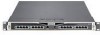
Check Point IP690 Security Platform Overview Check Point IP690 Security Platform Overview Figure 1 shows the component locations for the IP690. Figure 1 Component Locations Front View System status LEDs PMC NIC slots (slots 1 and 2) PC-card slot (slot 3) SLOT 1 SLOT 2 CONSOLE RESET AUX - Nokia IP690 | Installation Guide - Page 18
resellers. The Check Point support services group can only provide support for Check Point products that use Check Point-approved accessories. For sales or reseller information, contact the Check Point Support Center at http:// support.checkpoint.com/.. Console Port The default configuration of the - Nokia IP690 | Installation Guide - Page 19
be using IPSO 6.1 or greater. System Status LEDs You can visually monitor the status of the IP690 security platform by checking the system status LEDs. The system status LEDs are located on the center of the front panel, as shown in Figure 3. Check Point IP690 Security Platform Installation Guide - Nokia IP690 | Installation Guide - Page 20
the status LEDs for the installed ADP modules is described in Chapter 6, "Installing, Using, and Replacing ADP Services Modules." Note The Fault and Warning symbols in Table 4 are visible only if there is an alarm condition, as specified. 20 Check Point IP690 Security Platform Installation Guide - Nokia IP690 | Installation Guide - Page 21
. The IP690 supports using only one PC card at a time. Figure 4 Location of the PMC PC Card Carrier Slot SLOT 2 CONSOLE RESET AUX SLOT 3 SLOT 4 1 2 3 4 00578 PMC card carrier slot You can use the PC card flash memory to store local system logs. Check Point only supports PC cards purchased - Nokia IP690 | Installation Guide - Page 22
the Check Point Support Center at http://support.checkpoint.com/." on page 2. Note The slot that the PCMCIA card carrier uses also supports other PMC cards approved by Check Point. Power Supplies and Fan Unit The redundant power supplies and fan unit are located at the rear of the IP690 appliance - Nokia IP690 | Installation Guide - Page 23
a failed fan unit, see "Replacing a Fan Unit" on page 91. The system status LEDs on the front panel of the appliance show the status of the fan unit. For more information about the system status LEDs, see "System Status LEDs" on page 19. Check Point IP690 Security Platform Installation Guide 23 - Nokia IP690 | Installation Guide - Page 24
-1 firewall application For information about updates to the software requirements or additional applications that have become available since this guide was published, see the Check Point Support Center at http:// support.checkpoint.com/. 24 Check Point IP690 Security Platform Installation Guide - Nokia IP690 | Installation Guide - Page 25
to dispose of your waste equipment by handing it over to a designated collection point for the recycling of waste electrical and electronic equipment. The separate collection and city office or your household waste disposal service. Check Point IP690 Security Platform Installation Guide 25 - Nokia IP690 | Installation Guide - Page 26
1 Overview 26 Check Point IP690 Security Platform Installation Guide - Nokia IP690 | Installation Guide - Page 27
mounts in a standard 19-inch equipment rack with four mounting screws, as Figure 8 shows. Note To avoid damaging your equipment, Check Point recommends that you use all four rackmounting bolts when you install your appliance on the rack. Check Point IP690 Security Platform Installation Guide 27 - Nokia IP690 | Installation Guide - Page 28
Installing the Check Point IP690 Appliance Figure 8 Rack-Mounting Screw Locations SLOT 1 SLOT 2 CONSOLE RESET AUX SLOT 3 SLOT 4 1 2 3 4 IP690 is turned on. To rack-mount the appliance Caution The appliance is heavy. Use care when you remove it from the packaging. 1. Remove the appliance from - Nokia IP690 | Installation Guide - Page 29
the IP690. FAULT OVER TEMP OVER PWER OK FAULT OVER TEMP OVER PWER OK 00580 Power supplies b. Grasp the handle and release lever as shown in the following figure, and use the handle to firmly pull each power supply out of the chassis. 00588 Check Point IP690 Security Platform Installation Guide - Nokia IP690 | Installation Guide - Page 30
components. SLOT 1 SLOT 2 CONSOLE RESET AUX SLOT 3 1 2 3 4 SLOT 4 IP690 00597 SLOT 1 SLOT 2 CONSOLE RESET AUX SLOT 3 1 2 3 4 SLOT 4 IP690 c. Place the chassis tray assembly on a properly grounded surface. 00584 30 Check Point IP690 Security Platform Installation Guide - Nokia IP690 | Installation Guide - Page 31
CONSOLE RESET AUX SLOT 3 1 2 3 4 SLOT 4 IP690 00583 8. Reinstall the fan unit into the rear of the appliance. 9. Reinstall the power supplies. After you rack-mount the appliance, you can ground it by using the grounding lugs provided. Check Point IP690 Security Platform Installation Guide - Nokia IP690 | Installation Guide - Page 32
2 Installing the Check Point IP690 Appliance 32 Check Point IP690 Security Platform Installation Guide - Nokia IP690 | Installation Guide - Page 33
manually by using a console connection. It includes the following sections: „ Using a Console Connection „ Connecting Power and Turning the Power On „ Performing the Initial Configuration „ Connecting Network Interfaces „ Using Check Point Network Voyager „ Using the Command-Line Interface „ Using - Nokia IP690 | Installation Guide - Page 34
console or to a system running a terminal- emulation program. Connecting Power and Turning the Power On A power switch and a receptacle for the power cord are located on each power supply on the back of the appliance as shown in Figure 9. 34 Check Point IP690 Security Platform Installation Guide - Nokia IP690 | Installation Guide - Page 35
power is turned on to the power strip or wall receptacle into which you plugged the appliance. If the fans are still not running, or if the power LED does not illuminate, see the Check Point Support Center at http://support.checkpoint.com/. Check Point IP690 Security Platform Installation Guide - Nokia IP690 | Installation Guide - Page 36
DHCP to perform the initial configuration of your Check Point IP690 security platform, you must use a serial console connection (cable included). After you perform the initial configuration, you no longer need the console connection. To perform the initial configuration 1. Press the power switch to - Nokia IP690 | Installation Guide - Page 37
each NIC interface. The destination end of the cable can be either LC or SC, depending on the type of connector required for the destination Gigabit Ethernet device. For details, see "Fiber-Optic Gigabit Ethernet NIC Features" on page 53. Check Point IP690 Security Platform Installation Guide 37 - Nokia IP690 | Installation Guide - Page 38
you entered during the initial configuration and check that all cables are firmly connected. For more information, see the troubleshooting section in the installation guide for your appliance. Viewing Check Point IPSO Documentation by Using Check Point Network Voyager The following documentation - Nokia IP690 | Installation Guide - Page 39
is, you can view configuration settings, but you cannot change them. You can now execute CLI commands from the CLI shell and the Check Point IPSO shell. The Check Point IPSO shell is what you see when you initially log on to the appliance. Check Point IP690 Security Platform Installation Guide 39 - Nokia IP690 | Installation Guide - Page 40
image, inventory, and platform management of Check Point IP security platforms. Using Check Point Horizon Manager, an administrator can obtain configuration information, upgrade (or downgrade) the operating system, perform application installations, and distribute necessary licensing to multiple - Nokia IP690 | Installation Guide - Page 41
Deactivating Configured Interfaces If you are removing or replacing an installed NIC, use Check Point Network Voyager to deactivate any configured ports on the NIC before removing it. „ Deactivate all of the logical interfaces on the NIC. Check Point IP690 Security Platform Installation Guide 41 - Nokia IP690 | Installation Guide - Page 42
Note Before removing a configured network interface card with these instructions, you must deactivate the NIC by using Check Point Network Voyager. For additional information, see "Deactivating Configured Interfaces" on page 41. Use these instructions to install a NIC in the IP690. Some steps are - Nokia IP690 | Installation Guide - Page 43
side of the assembly, and completely remove the chassis tray assembly to expose the motherboard components. SLOT 1 SLOT 2 CONSOLE RESET AUX SLOT 3 1 2 3 4 SLOT 4 IP690 5. Place the chassis tray assembly on a table top. 00597 Check Point IP690 Security Platform Installation Guide 43 - Nokia IP690 | Installation Guide - Page 44
use. If you are removing an installed NIC, remove it by pulling up on the back of the NIC adjacent to the two interface connectors. 7. Insert the new NIC. a. Insert the NIC bezel into the front panel. SLOT 1 SLOT 2 CONSOLE RESET AUX 00592 44 Check Point IP690 Security Platform Installation - Nokia IP690 | Installation Guide - Page 45
tray assembly until it clicks into place. SLOT 1 SLOT 2 CONSOLE RESET AUX SLOT 3 1 2 3 4 SLOT 4 IP690 00583 The IPSO operating system automatically recognizes the NIC and applies the original configuration to the new NIC. Check Point IP690 Security Platform Installation Guide 45 - Nokia IP690 | Installation Guide - Page 46
Cards." Use Network Voyager to access detailed port information. For information about accessing Network Voyager, see "Using Check Point Network Voyager" on page 38. You can also use the tcpdump command to examine the track on a specific port. 46 Check Point IP690 Security Platform Installation - Nokia IP690 | Installation Guide - Page 47
Four-Port Copper Gigabit Ethernet NIC „ Two-Port Fiber-Optic Gigabit Ethernet NICs For instructions about how to add or replace NICs, see Chapter 4, "Installing and Replacing Network Interface Cards." The NICs supported in the Check Point IP690 security platform operate at the peripheral component - Nokia IP690 | Installation Guide - Page 48
PMC Network Interface Cards Four-Port 10/100 Ethernet NIC The IP690 supports Check Point-approved, four-port UTP5 dual-mode (10-Mbps and 100Mbps) Ethernet NICs installed in a PMC expansion slot. When you purchase a 10/100 Ethernet NIC with your IP690, the NIC is installed before the appliance - Nokia IP690 | Installation Guide - Page 49
or 100-Mbps hub or switch or a crossover cable to connect directly to a host. Use ANSI TIA/EIA-568-A/B compliant (Cat 5 or Cat 5e) unshielded twisted pair cable. You RX - Figure 13 shows the pin assignments for the RJ-45 cross-over cable. Check Point IP690 Security Platform Installation Guide 49 - Nokia IP690 | Installation Guide - Page 50
, you can use Network Voyager to set the port speed and full-duplex mode to 1000, 100, or 10 Mbps. For information about how to access Network Voyager and the related reference materials, see "Using Check Point Network Voyager" on page 38. 50 Check Point IP690 Security Platform Installation Guide - Nokia IP690 | Installation Guide - Page 51
you use in IP690 appliance must be the Version 2 type, as indicated on the right end of the NIC faceplate. These NICs are sold by Check Point under the order code NIF4425. After the power is NIC receptacles are for RJ-45 connectors. Check Point IP690 Security Platform Installation Guide 51 - Nokia IP690 | Installation Guide - Page 52
Cards Caution Cables that connect to the Gigabit Ethernet NIC must be ANSI TIA/EIA-568-A/B compliant (Cat 5 or Cat 5e) to prevent potential data loss. To connect to a 1-Gbps hub, switch, or router, use network configuration). Note You can use a Check Point IP690 Security Platform Installation Guide - Nokia IP690 | Installation Guide - Page 53
„ Compliance with IEEE 802.3z Gigabit Ethernet specification You can configure and monitor Gigabit Ethernet NIC interfaces with Check Point Network Voyager. Specifically, you set the port speed and full-duplex mode with Network Voyager. Check Point IP690 Security Platform Installation Guide 53 - Nokia IP690 | Installation Guide - Page 54
Interface Cards For information about how to access Network Voyager and the related reference materials, see "Using Check Point Network Voyager" on page 38. Figure 18 shows the front panel details for the two-port short-range (1000 BASE-SX) fiber-optic Gigabit Ethernet NIC you can use in IP690 - Nokia IP690 | Installation Guide - Page 55
are included with fiber-optic Gigabit Ethernet NICs. You can order additional cables from a cable vendor of your choice. Caution Cables that connect to the Gigabit Ethernet NIC must be IEEE 802.3z compliant to prevent potential data loss. Check Point IP690 Security Platform Installation Guide 55 - Nokia IP690 | Installation Guide - Page 56
5 Connecting PMC Network Interface Cards 56 Check Point IP690 Security Platform Installation Guide - Nokia IP690 | Installation Guide - Page 57
IP690 Appliance „ Configuration Example with VRRP Note In this chapter, network interface cards (NICs) refer to any installable PMC interface devices other than ADP modules. Check Point IP690 ADP modules help to accelerate firewall and VPN throughput. ADP is a technology designed to forward packets - Nokia IP690 | Installation Guide - Page 58
Getting Started Guide and Release Notes for the version of IPSO you are using and refer to both of these documents as needed as you complete the installation and configuration process. Use these instructions to install an ADP module in your appliance. Before You Begin To install a Check Point ADP - Nokia IP690 | Installation Guide - Page 59
"Check Point ADP Module Interface Names for IP690 Appliances" on page 68. 2. Upgrade the IPSO software to the required version as described in the Getting Started Guide and Release Notes that you received with your appliance. 3. Use Network Voyager or the command-line interface (CLI) to perform an - Nokia IP690 | Installation Guide - Page 60
are installed in an ADP module first to make the procedure easier. 9. Remove the two screws that secure the left air baffle and remove the baffle. Retain the baffle for future use. Reinstall the two baffle screws to secure the motherboard. 60 Check Point IP690 Security Platform Installation Guide - Nokia IP690 | Installation Guide - Page 61
Installing and Replacing ADP Modules Note It is important that you reinstall the two baffle screws for proper motherboard operation. Remove the two baffle screws and baffle, and reinstall the two screws SLOT 1 SLOT 2 00648 Check Point IP690 Security Platform Installation Guide 61 - Nokia IP690 | Installation Guide - Page 62
6 Installing, Using, and Replacing ADP Services Modules 10. If a FIPS screen is installed, note the position of the screen, as it must be reinstalled the same way. 't roll back, insert the module bezel into the front panel. As you lower 62 Check Point IP690 Security Platform Installation Guide - Nokia IP690 | Installation Guide - Page 63
module is completely seated into both connectors on the motherboard. 12. If the ADP module memory card is installed, you should remove it to provide access the retaining screw hole at the right side of don't have appropriate screws on hand. Check Point IP690 Security Platform Installation Guide 63 - Nokia IP690 | Installation Guide - Page 64
and configure the new ADP interfaces as described in "Configuring Check Point IPSO with IP690 ADP Interfaces" on page 67. Note the interface naming conventions in "Check Point ADP Module Interface Names for IP690 Appliances" on page 68. 64 Check Point IP690 Security Platform Installation Guide - Nokia IP690 | Installation Guide - Page 65
the configuration changes automatically. To identify whether a fiber transceiver you are using is short-range or long-range, refer to the color of the latch lever as follows: Type Short-range Long range Latch lever color Beige Blue Latch lever „ To install an ADP transceiver: Check Point IP690 - Nokia IP690 | Installation Guide - Page 66
Configuration page in Check Point Network Voyager, as shown in the following figure. Note The Non-Supported SFP Components table appears only if you have ADP transceivers installed that are not supported by Check Point. Check Point ADP Module LED Reference Information All Check Point IP690 - Nokia IP690 | Installation Guide - Page 67
Configuring Check Point IPSO with IP690 ADP Interfaces This section includes information about configuring IPSO to use the interfaces on a Check Point ADP module. To help you understand the implications of installing an ADP module, it provides an example of the steps you might perform to install - Nokia IP690 | Installation Guide - Page 68
. Using a configuration of this type can significantly degrade throughput. When you install an ADP module in an IP690 appliance, the network processor in the module performs all VPN encryption and decryption, even for VPN packets that are sent through PMC NIC interfaces. The built-in Check Point - Nokia IP690 | Installation Guide - Page 69
, legacy monitored-circuit VRRP is enabled and configured with these settings: „ Interface eth-s2p1c0 is assigned the IP address 10.1.1.1 and uses 10.1.1.99 as the VRRP backup address. „ Interface eth-s2p2c0 backs up interface eth-s2p1c0. Check Point IP690 Security Platform Installation Guide 69 - Nokia IP690 | Installation Guide - Page 70
information for those interfaces. If VRRP is active at that time, you will not be able to delete the configuration information for the interfaces used by VRRP. Therefore, you should begin by deleting the existing VRRP configuration. 70 Check Point IP690 Security Platform Installation Guide - Nokia IP690 | Installation Guide - Page 71
Configuring Check Point IPSO with IP690 ADP Interfaces Note It is best to perform the procedures in this section on the VRRP backup system first. When the installation is complete, the upgraded system can become the new master while you upgrade the original master. Reconfiguring Interfaces After you - Nokia IP690 | Installation Guide - Page 72
on this page, and you see a blue indicator next to each of them in the Up column. 3. Delete the interface names and configuration information for the interfaces you removed from slot 2 by following the remaining steps in this procedure. 72 Check Point IP690 Security Platform Installation Guide - Nokia IP690 | Installation Guide - Page 73
Configuring Check Point IPSO with IP690 ADP Interfaces Note To delete an interface used by VRRP or IP clustering, you must first disable the feature that uses the interface. This is why you deleted the VRRP configuration before you installed the ADP module. 4. Click a physical interface name. - Nokia IP690 | Installation Guide - Page 74
the address 10.1.1.1 to the new interface eth-s1p5c0. Reconfiguring VRRP After you finish reconfiguring interfaces, you need to reconfigure any protocols and features that used the removed interfaces to use the ADP interfaces. 74 Check Point IP690 Security Platform Installation Guide - Nokia IP690 | Installation Guide - Page 75
Interfaces In this example, you need to recreate the VRRP configuration using the new interfaces eth-s1p5c0 and eth-s1p6c0. The following figure shows the example system after you recreate the VRRP configuration using the new interfaces: Check Point IP690 Security Platform Installation Guide 75 - Nokia IP690 | Installation Guide - Page 76
6 Installing, Using, and Replacing ADP Services Modules 76 Check Point IP690 Security Platform Installation Guide - Nokia IP690 | Installation Guide - Page 77
) services modules in your Check Point IP690 appliance. The following topics are covered: „ Replacing the Compact Flash Memory Card „ Installing and Using a PC Card „ Installing a Hard-Disk Drive „ Replacing a Check Point Encryption Accelerator Card „ Replacing a Fan Unit „ Replacing a Power Supply - Nokia IP690 | Installation Guide - Page 78
turn the power off whenever you remove the chassis tray assembly to service internal components. Caution You risk damage to the appliance or loss of data if you do not use the following procedure when you replace the compact flash memory. 78 Check Point IP690 Security Platform Installation Guide - Nokia IP690 | Installation Guide - Page 79
Flash Memory Card To replace your compact flash 1. Use Check Point Network Voyager or the command-line interface (CLI) to perform an orderly shutdown of the IP690 appliance. For information about how to access Network Voyager and the related reference materials, see "Using Check Point Network - Nokia IP690 | Installation Guide - Page 80
care to prevent damaging components. SLOT 1 SLOT 2 CONSOLE RESET AUX SLOT 3 1 2 3 4 SLOT 4 IP690 9. Resecure the two chassis tray assembly retaining screws. 10. Turn on the power supplies at the back of the appliance. 00583 80 Check Point IP690 Security Platform Installation Guide - Nokia IP690 | Installation Guide - Page 81
card that is configured as an optional disk, system processes randomly fail because the system tries to find a /var directory on the optional disk. The resulting error messages indicate that some files in the /var directory are not available. Check Point IP690 Security Platform Installation Guide - Nokia IP690 | Installation Guide - Page 82
system. Installing a Hard-Disk Drive The IP690 is a flash-based appliance that also supports one or two optional hard-disk drives that plug into connectors on the motherboard. Each hard-disk drive contains 40 GB of storage space. Note A second hard-disk drive, which can be used for disk mirroring - Nokia IP690 | Installation Guide - Page 83
Use Check Point Network Voyager or the command-line interface (CLI) to perform an orderly shutdown of the IP690 appliance. For information about how to access Network Voyager and the related reference materials, see "Using Check Point Network Voyager" on page 38. 2. Turn off the power to the IP690 - Nokia IP690 | Installation Guide - Page 84
22 Location of Hard-Disk Drive on Chassis Tray Assembly SLOT 1 SLOT 2 CONSOLE RESET AUX SLOT 3 1 2 3 4 SLOT 4 IP690 Slot A Slot B 00579 Note In single hard-drive configurations, install the hard-disk drive in Slot A first. 84 Check Point IP690 Security Platform Installation Guide - Nokia IP690 | Installation Guide - Page 85
Installing a Hard-Disk Drive 6. Remove the four screws from the base of the hard-disk drive and remove the hard-disk drive. 00593 7. Slide the new hard-disk drive onto the mounting locations. 00582 8. Replace the four screws. 00593 Check Point IP690 Security Platform Installation Guide 85 - Nokia IP690 | Installation Guide - Page 86
The IP1560 comes with the Check Point encryption accelerator card preinstalled as part of its base bundle to further enhance VPN performance. The encryption accelerator card provides high-speed cryptographic processing that enhances VPN performance. The IP690 appliance uses a PMC format encryption - Nokia IP690 | Installation Guide - Page 87
card 1. Use Check Point Network Voyager or the command-line interface (CLI) to perform an orderly shutdown of the IP690. For information about how to access Network Voyager and the related reference materials, see "Using Check Point Network Voyager" on page 38. 2. Turn off the power to the IP690 - Nokia IP690 | Installation Guide - Page 88
SLOT 4 IP690 00597 5. Locate the PMC encryption accelerator card on the motherboard. The encryption card is located on the back left side of the motherboard. SLOT 1 SLOT 2 CONSOLE RESET AUX SLOT 3 1 2 3 4 SLOT 4 IP690 00585.1 88 Check Point IP690 Security Platform Installation Guide - Nokia IP690 | Installation Guide - Page 89
with each other. The four screw holes and four standoffs should also be aligned with each other. 8. Push down on the right side of the card above the interface connectors until it is properly seated on the motherboard. Check Point IP690 Security Platform Installation Guide 00518.1 89 - Nokia IP690 | Installation Guide - Page 90
system, so the appliance automatically detects and configures the Check Point encryption accelerator card. For the Check Point IP690 appliances, SecureXL is on by default. After you install the Check Point encryption accelerator card and reboot the appliance, SecureXL automatically uses the card - Nokia IP690 | Installation Guide - Page 91
(CLI) to perform an orderly shutdown of the IP690. For information about how to access Network Voyager and the related reference materials, see "Using Check Point Network Voyager" on page 38. 2. Turn off power to the IP690 appliance. Check Point IP690 Security Platform Installation Guide 91 - Nokia IP690 | Installation Guide - Page 92
-264VAC. The power supply output is regulated to a tolerance of ± 5 percent of the specified output voltage. Before You Begin To install or replace a power supply, you need: „ Physical access to the appliance „ A replacement power supply 92 Check Point IP690 Security Platform Installation Guide - Nokia IP690 | Installation Guide - Page 93
before you touch any component. To replace a power supply 1. Use Check Point Network Voyager or command-line interface (CLI) to perform an orderly shutdown of the IP690 appliance. For information about how to access Network Voyager, see Using Check Point Network Voyager on page 38. 2. Locate the - Nokia IP690 | Installation Guide - Page 94
on the power. Monitoring the IP690 Appliance Power Supply You can monitor the status of the IP690 appliance power supplies with Check Point Network Voyager. Similarly, you can also use the command-line interface (CLI). For information about 94 Check Point IP690 Security Platform Installation Guide - Nokia IP690 | Installation Guide - Page 95
the grounding strap included in the battery replacement kit. To install the battery, perform the following tasks: 1. Use Check Point Network Voyager or the command-line interface (CLI) to perform an orderly shutdown of the IP690. For information about how to access Network Voyager and the related - Nokia IP690 | Installation Guide - Page 96
Use a small nonconductive device, such as a plastic probe, to slide the battery out of the battery holder through the cutout in the holder. 8. With the positive side facing up, slide the new battery through the cutout in the battery holder. 96 Check Point IP690 Security Platform Installation Guide - Nokia IP690 | Installation Guide - Page 97
://support.checkpoint.com/. 12. Reset the appliance date and time information by using Check Point Network Voyager or the command-line interface. The battery is required to maintain the date and time whenever you shut down the appliance. Check Point IP690 Security Platform Installation Guide 97 - Nokia IP690 | Installation Guide - Page 98
7 Installing and Replacing Components Other than Network Interface Cards (NICs) and Accelerated Data Path 98 Check Point IP690 Security Platform Installation Guide - Nokia IP690 | Installation Guide - Page 99
set for flow control. Solution The IP690 does not use flow control. The terminal should be set for no flow control. Problem Defective IP690 or file system. Solution See the Check Point Support Center at http://support.checkpoint.com/. Check Point IP690 Security Platform Installation Guide 99 - Nokia IP690 | Installation Guide - Page 100
changed and is now newpassword. Finally, return the entire database to its default settings and bring up the new system-startup procedure. The new system-startup procedure is described in Chapter 3, "Performing the Initial Configuration". 100 Check Point IP690 Security Platform Installation Guide - Nokia IP690 | Installation Guide - Page 101
default configuration. 3. Create the new default configuration. Do Not Get a Login Prompt-Error Messages Appear Problem The IP690 is defective, or the file system on the IP690 is defective. Solution See the Check Point Support Center at http://support.checkpoint.com/. Note Use the full installation - Nokia IP690 | Installation Guide - Page 102
isolate the problem. Use tcpdump to verify that a packet is leaving or entering a port. Problem Interfaces not up. Solution Ensure that all interfaces are up and active, as described in Chapter 3, "Performing the Initial Configuration." 102 Check Point IP690 Security Platform Installation Guide - Nokia IP690 | Installation Guide - Page 103
" on page 38. Problem No IP connectivity. Solution Verify that you have IP connectivity; ping various hosts on each network. Problem DVMRP is not enabled on the interfaces. Solution Verify that DVMRP is enabled on the interfaces in use. Check Point IP690 Security Platform Installation Guide 103 - Nokia IP690 | Installation Guide - Page 104
. Appliance Does Not Recognize New Memory Configuration Problem DIMMs are not properly seated in DIMM sockets. Solution Repeat memory installation procedures. Make sure DIMMs are fully seated in sockets. Be sure DIMMs click into place. 104 Check Point IP690 Security Platform Installation Guide - Nokia IP690 | Installation Guide - Page 105
example: BOOTMGR[11]>printenv NOKIAIPSOBOOTMGRVERSION=4.0.1-DEV00110.18.2005-115113 autoboot:YES testboot:NO bootwait:3 boot-file:/image/current/kernel boot-flags: boot-device:wd0 vendor:Nokia model:IP bmslice:1 BOOTMGR[12]> Check Point IP690 Security Platform Installation Guide 105 - Nokia IP690 | Installation Guide - Page 106
. When a trace is enabled the output appears in /var/tmp/ ipsrd.log. Common Problems with OSPF Use tcpdump to view routing information. Use the following command display routing updates for that interface: tcpdump -i interface proto ospf 106 Check Point IP690 Security Platform Installation Guide - Nokia IP690 | Installation Guide - Page 107
subnet masks; change to RIP version 2 or OSPF to use inconsistent subnet masks. Problem Number of networks exceeds the RIP limit. Solution RIP can span up to 16 networks. Verify that your network topology does not exceed this limit. Check Point IP690 Security Platform Installation Guide 107 - Nokia IP690 | Installation Guide - Page 108
routes involves several configuration steps. Follow the tasks in the Voyager Reference Guide to ensure that you follow all steps. For information about how to access Network Voyager and the related reference materials, see "Using Check Point Network Voyager" on page 38. Problem Routing protocol is - Nokia IP690 | Installation Guide - Page 109
Other Specifications Maximum altitude of operation Operating temperature range Input voltage requirement Current Power consumption To 10, 000 feet or 3300 meters above sea level 41 to 104° Fahrenheit 5 to 40° Celsius 100 VAC or 240 VAC, 50 or 60 Hz 4A 250 watts per power supply Check Point IP690 - Nokia IP690 | Installation Guide - Page 110
A Technical Specifications 110 Check Point IP690 Security Platform Installation Guide - Nokia IP690 | Installation Guide - Page 111
Nokia, Inc. Manufacturer's Address: 313 Fairchild Drive Mountain View, CA 94043-2215 USA declares that the product: Product Name: Model Number: Product Options: Serial Number: Date First Applied: IP690 EM7900 with Amendment 93/68/EEC. Check Point IP690 Security Platform Installation Guide 111 - Nokia IP690 | Installation Guide - Page 112
B Compliance Information Christopher Saleem Compliance & Reliability Engineering Manager Security & Mobile Connectivity, Enterprise Solutions Mountain View, California May 2007 112 Check Point IP690 Security Platform Installation Guide - Nokia IP690 | Installation Guide - Page 113
radiate radio frequency energy and, if not installed and used in accordance with the instruction manual, may cause harmful interference to radio communications. Operation of this equipment in a residential area is likely to cause harmful Check Point IP690 Security Platform Installation Guide 113 - Nokia IP690 | Installation Guide - Page 114
case the user will be required to correct the interference at his own expense. Caution Any changes or modifications not expressly approved by the grantee of this device could void the user's authority to operate the equipment. 050316 114 Check Point IP690 Security Platform Installation Guide - Nokia IP690 | Installation Guide - Page 115
16 commands ICLID 106 compact flash memory card 15 replacing 78 compliance statements 113 component locations 17 configuring interfaces 46 connecting network interfaces 37 connections copper Gigabit Ethernet NIC 51 Ethernet NIC 49 fiber-optic Gigabit Ethernet NIC 54 modem 19 power 34 console cable - Nokia IP690 | Installation Guide - Page 116
cable 34 O operating system requirements 24 P PC card 16 flash memory 21 installing and using 81 removing 82 PCMCIA 15 physical dimensions 109 pin assignments console connection 18 PMC connector 89 expansion slots 41 power connections 34 power cord rating 24 power supplies 15 location 22 replacing - Nokia IP690 | Installation Guide - Page 117
specifications 109 troubleshooting 99 V vertical space requirements 109 voltage fluctuation 113 voltage requirements 22 VPN performance 86 VT100-compatible terminal 34 W warning notices 12 weight 109 width 109 Y yellow LED 20, 23 Check Point IP690 Security Platform Installation Guide Index - Nokia IP690 | Installation Guide - Page 118
Index - 118 Check Point IP690 Security Platform Installation Guide
-
 1
1 -
 2
2 -
 3
3 -
 4
4 -
 5
5 -
 6
6 -
 7
7 -
8
-
9
-
10
-
11
-
12
-
13
-
14
-
15
-
16
-
17
-
18
-
19
-
20
-
21
-
22
-
23
-
24
-
25
-
26
-
27
-
28
-
29
-
30
-
31
-
32
-
33
-
34
-
35
-
36
-
37
-
38
-
39
-
40
-
41
-
42
-
43
-
44
-
45
-
46
-
47
-
48
-
49
-
50
-
51
-
52
-
53
-
54
-
55
-
56
-
57
-
58
-
59
-
60
-
61
-
62
-
63
-
64
-
65
-
66
-
67
-
68
-
69
-
70
-
71
-
72
-
73
-
74
-
75
-
76
-
77
-
78
-
79
-
80
-
81
-
82
-
83
-
84
-
85
-
86
-
87
-
88
-
89
-
90
-
91
-
92
-
93
-
94
-
95
-
96
-
97
-
98
-
99
-
100
-
101
-
102
-
103
-
104
-
105
-
106
-
107
-
108
-
109
-
110
-
111
-
112
-
113
-
114
-
115
-
116
-
117
-
118
 |
 |

Part No. N450000890 Rev 001
Published March 2009
Check Point
IP690 Security Platform
Installation Guide