Nokia IP740 Installation Guide
Nokia IP740 - Remote Access Server Manual
 |
View all Nokia IP740 manuals
Add to My Manuals
Save this manual to your list of manuals |
Nokia IP740 manual content summary:
- Nokia IP740 | Installation Guide - Page 1
IP700 Series Installation Guide Part Number: N450436003 Rev B April 2004 - Nokia IP740 | Installation Guide - Page 2
at FAR 52.227-19. IMPORTANT NOTE TO USERS This software and hardware is provided by Nokia Corporation as is and any express or implied warranties damages (including, but not limited to, procurement of substitute goods or services; loss of use, data, or profits; or business interruption) however - Nokia IP740 | Installation Guide - Page 3
, Summit Avenue Southwood, Farnborough Hampshire GU14 ONG U.K Asia-Pacific Web Site: Email: Voice: Fax: Voice: Fax: Voice: Fax: Nokia Customer Support https://support.nokia.com/ [email protected] Americas 1-888-361-5030 or 1-613-271-6721 1-613-271-8782 Europe +44 (0) 125-286-8900 +44 (0) 125 - Nokia IP740 | Installation Guide - Page 4
- Nokia IP740 | Installation Guide - Page 5
This Guide 11 About Nokia IP700 Series Network Security Platforms 12 IP700 Series Documentation 13 Structure of This Guide 14 Conventions Used in This Guide 16 CHAPTER 1 Overview 19 About the IP700 Series Platform 19 Site Requirements 22 CHAPTER 2 Installing the IP700 Series Appliance - Nokia IP740 | Installation Guide - Page 6
a Power Supply 61 Upgrading the Memory 64 CHAPTER 4 Configuring and Monitoring the IP700 Series Appliance 75 Entering the Hostname 76 Devices 104 Connecting to a Modem 107 CHAPTER 6 Installing the Nokia Encryption Accelerator Card 109 Installing the Encryption Accelerator Card 110 Enabling - Nokia IP740 | Installation Guide - Page 7
General Troubleshooting Information 133 CHAPTER 9 Using tcpdump 147 tcpdump Command Basics 148 Filtering Traffic With tcpdump 149 Saving tcpdump Results to a Local File 150 CHAPTER 10 Tips for Installing, Configuring, and Maintaining Your Appliance 153 APPENDIX A Technical Specifications 155 - Nokia IP740 | Installation Guide - Page 8
Contents APPENDIX C General Public Licensed Software 167 GNU GENERAL PUBLIC LICENSE 168 APPENDIX D Warranty and Software License 171 APPENDIX E Glossary of Abbreviations 175 Index 177 8 IP700 Series Installation Guide - Nokia IP740 | Installation Guide - Page 9
the E1 Cable 97 E1 Crossover Cable Pin Connections 98 8-pin female (host 98 Typical Nokia T1 Network Interface Card Front Panel Details 100 Output Connector for the T1 Cable 101 Card Front Panel Details . . . . . 105 Pin assignments for modem connections 107 IP700 Series Installation Guide 9 - Nokia IP740 | Installation Guide - Page 10
Figures 10 IP700 Series Installation Guide - Nokia IP740 | Installation Guide - Page 11
About This Guide This preface provides the following information: • About Nokia IP700 Series Network Security Platforms (see page 12) • IP700 Series Documentation (see page 13) • Structure of This Guide (see page 14) • Conventions Used in This Guide (see page 16) IP700 Series Installation Guide 11 - Nokia IP740 | Installation Guide - Page 12
rate in a single package in the industry sets a new standard for firewall and virtual private network (VPN) solutions. Ideally suited to provide secure Internet connectivity, the IP710 and IP740 combine high-performance, high-availability IP routing with a complete implementation of the Check Point - Nokia IP740 | Installation Guide - Page 13
the IP700 Series Installation Guide in both HTML and PDF formats on the World Wide Web support site (https://support.nokia.com/). You can access inline help when you use Voyager. Inline help is the context-sensitive information source for Voyager. To enable inline help for a specific subject, click - Nokia IP740 | Installation Guide - Page 14
6, Installing the Nokia Encryption Accelerator Card explains how to install and enable the accelerator card. • CHAPTER 7, Using the Boot Manager explains how to use the boot manager, which is part of the built-in IPSO software. • CHAPTER 8, Troubleshooting discusses problems you might encounter - Nokia IP740 | Installation Guide - Page 15
software that comes with the appliance. • APPENDIX D, Warranty and Software License contains Nokia warranty and software license information. • APPENDIX E, Glossary of Abbreviations provides definitions to acronyms and initialisms used throughout the guide. IP700 Series Installation Guide 15 - Nokia IP740 | Installation Guide - Page 16
Conventions Used in This Guide This section describes the conventions used in text, examples, and graphics. Typeface/ Meaning Italic • Link, data entry location . This is the Overview chapter. Click CONFIG. Hostname? Type ser-s1p2 to configure the interface. 16 IP700 Series Installation Guide - Nokia IP740 | Installation Guide - Page 17
Conventions Used in This Guide WARNING: Shows critical information that, if ignored, could cause injuries to you or to other people, damage to equipment, ! compromise the system, or would cause data loss. NOTE: Calls special attention to important information. IP700 Series Installation Guide 17 - Nokia IP740 | Installation Guide - Page 18
About This Guide 18 IP700 Series Installation Guide - Nokia IP740 | Installation Guide - Page 19
Nokia IP700 Series platform combines the power of IPSO software with your choice of applications. Each IP700 Series appliance consists of components in three primary categories: • Nokia hardware • Selected network interface cards • Designated software applications IP700 Series Installation Guide - Nokia IP740 | Installation Guide - Page 20
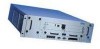
(10/100 Mbps) Rear View Hard-Disk Drive 00082 PCMCIA Slot Modem port Console port 00086 Power supplies The IP700 Series appliance can support two power supplies. In addition, the IP700 Series appliance can house two disk drive units. However, the feature of mirrored disk drives will only be - Nokia IP740 | Installation Guide - Page 21
includes a PCMCIA slot that supports PCMCIA modems. NOTE: Nokia products support only Nokia cards. The Nokia Customer Support Department supports Nokia cards purchased either from Nokia Inc. or approved resellers. Contact Nokia for sales or reseller information. IP700 Series Installation Guide 21 - Nokia IP740 | Installation Guide - Page 22
Series appliance, ensure that your computer room or wiring closet conforms to the environmental specifications listed in APPENDIX A, Technical Specifications. WARNING: Using controls, making adjustments in performance batteries according to the manufacturer's instructions. WARNING: To reduce the - Nokia IP740 | Installation Guide - Page 23
Nokia IP700 Series appliance, configure the system, connect it to your network, and monitor it. See these topics for instructions to perform • Monitoring the Appliance (see page 33) Caution: Protect your IP700 Series appliance and other electronic ! equipment from static discharge by making sure - Nokia IP740 | Installation Guide - Page 24
Series Appliance IPSO Version Requirements To run an IP710 appliance, you must use IPSO v3.5 or higher. To run an IP740 configured DHCP server to provide your IP700 Series appliance with the host name, IP Series appliance to password. To use DHCP to configure your system, follow the instructions - Nokia IP740 | Installation Guide - Page 25
Series appliance serial number or the static MAC address of the IP700 Series appliance NIC the DHCP server communicates with. The minimum IP address lease required is one year. NOTE: Either the DHCP server must be on the same network as your Nokia IP700 Series NIC IP700 Series Installation Guide 25 - Nokia IP740 | Installation Guide - Page 26
hardware ethernet 00:a0:8e:20:00:61; # serial number of the box option dhcp-client-identifier "123456"; fixed-address 10.1.1.11; option host-name "IP710"; Run the DHCP Client on the IP700 Series Appliance NOTE: Do not perform this procedure unless you have configured an appropriate DHCP server with - Nokia IP740 | Installation Guide - Page 27
the problem, follow these steps: 1. Establish a console connection to the system. 2. Enter the following: rm /config/active or mv /config/active /config/active.old 3. Reboot the IP700 Series appliance. 4. Respond to the configuration prompts in a timely manner. IP700 Series Installation Guide 27 - Nokia IP740 | Installation Guide - Page 28
Supply Switches 00086 Perform the following steps for each power supply: 1. Connect the power cord securely into the power socket on the back of the IP700 Series appliance. Plug power supply can safely power the IP700 Series appliance. 2. Press the switch on the power supply to activate the IP700 - Nokia IP740 | Installation Guide - Page 29
running, check the power supply cord to make sure it is properly connected. If the fans are still not running after this check, contact technical support. See "Nokia Contact Information" on page 3 for more information. IP700 Series Installation Guide 29 - Nokia IP740 | Installation Guide - Page 30
, you can skip these instructions. To connect to the console, follow these steps: 1. Select a console from the following list: • Any standard VT100- front panel of the IP700 Series appliance. NOTE: Use the left port; the right port is an auxiliary modem port. 30 IP700 Series Installation Guide - Nokia IP740 | Installation Guide - Page 31
Connecting to the Console NOTE: If you connect the console port to a data communications equipment (DCE) device, use a straight-through cable. Component Location 00082 Console port IP700 Series Installation Guide 31 - Nokia IP740 | Installation Guide - Page 32
Chapter 2: Installing the IP700 Series Appliance The following figure provides pin assignment information for console and modem-port connections. Input/ Pin# Assignment manager. 5. After some miscellaneous output appears, the following prompt appears: Hostname? 32 IP700 Series Installation Guide - Nokia IP740 | Installation Guide - Page 33
prompt yet. CHAPTER 4, Configuring and Monitoring the IP700 Series Appliance contains software configuration instructions. NOTE: If the hostname message does not appear on following figure. Appliance Status LEDs IP700 Series Installation Guide 00082 Fault (Red) Alarm (Yellow) Power On (Green) 33 - Nokia IP740 | Installation Guide - Page 34
Series Appliance You can find the secondary status LEDs in the locations listed in the following table. To find information about these status LEDs, refer to the page numbers Panel Details" on page 96. See "Typical Nokia T1 Network Interface Card Front Panel Details" on Series Installation Guide - Nokia IP740 | Installation Guide - Page 35
this chapter provides instructions on how to do so, including tasks related to installing, monitoring, and replacing components associated with your IP700 Series appliance: • Network and Replacing a Power Supply (see page 61) • Upgrading the Memory (see page 64) IP700 Series Installation Guide 35 - Nokia IP740 | Installation Guide - Page 36
on the top edge of the face plate. Network Interface Card Preinstallation Considerations The IP700 Series platform connects to your installed network interface cards through two cPCI busses (bus A and Locations Slot 1 Slot 2 Slot 3 Slot 4 00101 Bus A Bus B 36 IP700 Series Installation Guide - Nokia IP740 | Installation Guide - Page 37
performance. In the IP710, each cPCI bus runs only at 33 Mhz. This section provides answers to the following questions, which should help you obtain the best performance my IP700 Series appliance for optimum performance? Circumstances Under Which the cPCI Busses Change Speed in the IP740 The bus - Nokia IP740 | Installation Guide - Page 38
Series Platforms The following 66-Mhz and 33-Mhz cards are available from Nokia. Network Interface Card 10/100 Mbps Ethernet Gigabit Ethernet V.35 X.21 E1 T1 ATM Operating Speed of Operating Speed of IP710 IP740 to attain optimum performance from those cards. 38 IP700 Series Installation Guide - Nokia IP740 | Installation Guide - Page 39
If you install a 33-Mhz card in one of the IP740 appliance slots, that bus runs at 33 Mhz. Therefore, if IP700 Series appliances with six available gigabit Ethernet ports each (for a total of twelve ports) to provide a highavailability firewall with performance. IP700 Series Installation Guide 39 - Nokia IP740 | Installation Guide - Page 40
Backup Traffic #1 Port 00241 Card Type dual-port gigabit Ethernet dual-port gigabit Ethernet single-port gigabit Ethernet single-port gigabit Ethernet Slot # 1 2 3 4 40 IP700 Series Installation Guide - Nokia IP740 | Installation Guide - Page 41
Link Link Tx Tx Rx Rx Link Link IP700 ISP Internet Extranet 00240 For further information about VRRP and DMZ configurations, see the Voyager Reference Guide. IP700 Series Installation Guide 41 - Nokia IP740 | Installation Guide - Page 42
in the IP740 If card was previously present on that bus. Reboot your IP740 appliance to reset the bus speed to 66 Mhz. page 81. Hot Plugging a 33-Mhz Card in the IP740 If you hot plug a 33-Mhz card in any the bus is running at 66 Mhz in the IP740 appliance, you must reboot after you insert the card - Nokia IP740 | Installation Guide - Page 43
Preinstallation Considerations" on page 36. 2. Use a screwdriver to remove the retaining screws that hold the blank panel in place. 00085 3. Remove the blank panel. IP700 Series Installation Guide 43 - Nokia IP740 | Installation Guide - Page 44
place. Take care to make sure that the card edge is completely seated into the connector inside the IP700 Series appliance. If the card has an ejector, you can use it to assist in the final seating of Using Voyager to Configure the Network Interfaces" on page 81. 44 IP700 Series Installation Guide - Nokia IP740 | Installation Guide - Page 45
Network Interface Cards The following table lists the network interface cards that include Panel Details" on page 96 For information about the LEDs, see "Typical Nokia T1 Network Interface Card Front Panel Details" on page 100 For information about page 105 IP700 Series Installation Guide 45 - Nokia IP740 | Installation Guide - Page 46
Interface Card The following procedure applies to all network interface cards: 1. Use Voyager to perform the following: a. Deactivate all of the logical interfaces on the card. b. Deactivate a screwdriver to remove the retaining screws that hold the card. 00085 46 IP700 Series Installation Guide - Nokia IP740 | Installation Guide - Page 47
Removing a Network Interface Card 3. Gently pull the card forward from the card slot. If the card has an ejector, use it to assist you in removing the card from the slot. 00084 IP700 Series Installation Guide 47 - Nokia IP740 | Installation Guide - Page 48
Chapter 3: Installing, Monitoring, and Replacing Components 4. Cover the empty slot with a blank panel and screw the retaining screws into place. NOTE: The blank panel goes in only one way, with the EMI fingers up. 00096 48 IP700 Series Installation Guide - Nokia IP740 | Installation Guide - Page 49
all network interface cards: 1. See "Network Interface Card Preinstallation Considerations" on page 36. 2. Use a screwdriver to remove the retaining screws that hold the card. IP700 Series Installation Guide 00085 49 - Nokia IP740 | Installation Guide - Page 50
Chapter 3: Installing, Monitoring, and Replacing Components 3. Gently pull the card forward from the card slot. If the card has an ejector, use it to assist you in removing the card from the slot. 00084 50 IP700 Series Installation Guide - Nokia IP740 | Installation Guide - Page 51
assist in the final seating of the card. 00084 5. Screw the retaining screws into place. The IP700 Series appliance detects the card. 6. If you replaced the card with a card of a different type, use Voyager to Configure the Network Interfaces" on page 81. IP700 Series Installation Guide 51 - Nokia IP740 | Installation Guide - Page 52
Series appliance supports a Nokia-approved PCMCIA modem card that allows you to set the country code through Voyager. For information about the country codes, see the Voyager Reference Guide. To use a modem with the IP700 Series click on the Network Access and Services link in the Security and Access - Nokia IP740 | Installation Guide - Page 53
. Until hot swapping becomes a supported feature in IPSO, do not use the hot swap switch on any IP700 Series appliance. Back up your hard drive files to a remote system on a regular basis. For the procedure for backing up and restoring files, see the IPSO Getting Started Guide and Release Notes. In - Nokia IP740 | Installation Guide - Page 54
page 55. One of the following: • The system is booting • The drive unit is starting up • The system is testing the drive unit 54 IP700 Series Installation Guide - Nokia IP740 | Installation Guide - Page 55
when removing the ! hard-disk drive unit can result in damage to the unit or data loss. To perform an orderly shut down of the operating system, follow these steps: 1. On the Voyager home page for the drive unit is off before proceeding to the next step. IP700 Series Installation Guide 55 - Nokia IP740 | Installation Guide - Page 56
drive unit . 00085 8. Gently pull the hard disk-drive unit forward from the card slot and remove the hard-disk drive unit . 00100 56 IP700 Series Installation Guide - Nokia IP740 | Installation Guide - Page 57
unit with the appropriate software. For further information, contact the appropriate Nokia customer support site as listed in "Nokia Contact Information" on page 3. NOTE: Make sure you replace the new into the connector inside the IP700 Series appliance. . IP700 Series Installation Guide 00100 57 - Nokia IP740 | Installation Guide - Page 58
Chapter 3: Installing, Monitoring, and Replacing Components 3. Screw the retaining screws into place. 00085 4. Switch on the IP700 Series appliance. 58 IP700 Series Installation Guide - Nokia IP740 | Installation Guide - Page 59
: Components inside the chassis can overheat if they are not ! cooled for even short periods of time. If you keep the power to the IP700 Series appliance on, do not allow the fan tray to remain out of the chassis for any longer than is necessary. 1. Unscrew the screws that hold - Nokia IP740 | Installation Guide - Page 60
Chapter 3: Installing, Monitoring, and Replacing Components 2. Pull the fan tray forward to remove it from the chassis. 00088 3. Slide the new fan tray into the chassis. 00088 4. Screw in the retaining screws. 60 IP700 Series Installation Guide - Nokia IP740 | Installation Guide - Page 61
OK (green) Performing within specifications Fault (red) Not performing within specifications Over Temp (yellow) Power supply has overheated Access the power supply from the back of the IP700 Series appliance. To remove the power supply, follow these steps. IP700 Series Installation Guide 61 - Nokia IP740 | Installation Guide - Page 62
-fan blade assembly is no longer turning. 3. Use a screwdriver to unscrew the two screws that hold the power supply to the chassis. 00099 62 IP700 Series Installation Guide - Nokia IP740 | Installation Guide - Page 63
power supply into place. 00087 6. Replace the retaining screws and screw them into place. 7. Reconnect the power cord. 8. Turn on the power supply switch. IP700 Series Installation Guide 63 - Nokia IP740 | Installation Guide - Page 64
resellers. For further information, contact the appropriate Nokia customer support site as listed in "Nokia Contact Information" on page 3. The IP700 Series appliance base system contains four dual inline memory module (DIMM) sockets. The IP740 appliance base system ships with either 512 MB - Nokia IP740 | Installation Guide - Page 65
number of Nokia memory upgrade kits, each of which includes two 256-MB Dual Inline Memory Series appliance, be sure to turn off power to the appliance. Caution: To protect the IP700 Series appliance and protect memory or Lynx to perform an orderly shutdown of the IP700 Series appliance. For detailed - Nokia IP740 | Installation Guide - Page 66
Chapter 3: Installing, Monitoring, and Replacing Components 3. Turn off both power switches on the rear of the appliance and remove both power cords from the power supplies. Confirm that the two cooling-fan blade assemblies are no longer turning. 00099 66 IP700 Series Installation Guide - Nokia IP740 | Installation Guide - Page 67
Accessing and Removing the Existing DIMMs To install the memory upgrade kit, use the following procedure. 1. Remove the two power supplies as follows (removing the Use a screwdriver to unscrew the two screws that secure each power supply to the chassis. 00099 IP700 Series Installation Guide 67 - Nokia IP740 | Installation Guide - Page 68
Chapter 3: Installing, Monitoring, and Replacing Components b. Grasp each power-supply handle and firmly pull each power supply toward you. 00087 2. Loosen the four front-panel thumbscrews indicated in the following figure. 00085 68 IP700 Series Installation Guide - Nokia IP740 | Installation Guide - Page 69
Upgrading the Memory 3. Slide the chassis assembly forward to expose the motherboard components, as the following figure shows. 00171 IP700 Series Installation Guide 69 - Nokia IP740 | Installation Guide - Page 70
look at the appliance from the front, as the following figure shows. DIMM Socket Locations Front of Motherboard Installing the New DIMMs in the IP700 Series Appliance You can upgrade the memory of the IP700 Series appliance to 1 GB by inserting two additional 256 MB DIMMs. 70 IP700 - Nokia IP740 | Installation Guide - Page 71
Upgrading the Memory For each DIMM you remove from your IP700 series appliance, perform the following procedure. NOTE: The figures free it from the contact pins. 00121b NOTE: IP700 Series appliances use interleaved memory and work in pairs. Therefore, two DIMMs would not be installed in - Nokia IP740 | Installation Guide - Page 72
into the lock position as you press the DIMM into place. Pressing DIMMs Into DIMM Sockets 00121d Final Installation Steps After you install the DIMMs, perform the following procedure: 1. Slide the chassis assembly back into the appliance and resecure the four thumbscrews. 72 IP700 - Nokia IP740 | Installation Guide - Page 73
place. 00087 3. Replace the retaining screws and screw them into place. 4. Reattach the power cords. 5. Turn on the power. The appliance automatically recognizes the new memory configuration. You can verify this from the Voyager or Lynx interface. IP700 Series Installation Guide 73 - Nokia IP740 | Installation Guide - Page 74
Chapter 3: Installing, Monitoring, and Replacing Components 74 IP700 Series Installation Guide - Nokia IP740 | Installation Guide - Page 75
(see page 81) The first time you turn the power on for the IP700 Series appliance, the system-startup procedure runs. Using the system-startup procedure, you assign a program. For information about using Voyager, see the Voyager Reference Guide and the Voyager inline help, both of which you can - Nokia IP740 | Installation Guide - Page 76
for the IP700 Series appliance. Alphanumeric including the domain of the IP700 Series appliance, then confirm your entry permissions on the IP700 Series appliance. Passwords are follows: You can configure your Nokia system in two ways. choice [1-2, q]: Type the number corresponding to the browser you - Nokia IP740 | Installation Guide - Page 77
1 if the IP700 Series appliance is connected to the host for your browser cannot be reached from the IP700 Series appliance by using a default route (you do not have a serial-port console connection. Lynx browser software is supplied as part of the standard IPSO software on the appliance. If you - Nokia IP740 | Installation Guide - Page 78
Series appliance from the host that runs your browser. System startup searches for all of the connected interfaces and displays a list number adjacent to the physical IDs that appear. Your selection determines the interface you use to access the IP700 Series appliance IP700 Series Installation Guide - Nokia IP740 | Installation Guide - Page 79
you selected an Ethernet, FDDI interface, enter the IP address of the system-default IP700 Series appliance. If you selected an ATM or serial interface, the default route automatically sets the parameters, just as you do if you select a serial interface IP700 Series Installation Guide 79 - Nokia IP740 | Installation Guide - Page 80
calls on the modem (Y/N) • If enabled, a number for the dial-back feature In Voyager, see Configuration: Security and Access Configuration: Network Access and Services: Modem Configuration. Additional configuration in Voyager is required to set up the modem. 80 IP700 Series Installation Guide - Nokia IP740 | Installation Guide - Page 81
on the host you will use to complete configuration of the IP700 Series appliance. In the Location or Address field, enter the IP address have a network connection between the host and your IP700 Series appliance. Confirm the information you entered during the initial configuration and check - Nokia IP740 | Installation Guide - Page 82
Series Appliance Accessing Voyager Reference Information The following reference information is available to you as you use the Voyager system: Voyager Reference Guide DOC. You can also access the Voyager Reference Guide at the Nokia support site (https://support.nokia.com) or on the CD that was - Nokia IP740 | Installation Guide - Page 83
source for Voyager. To enable inline help for a specific subject, click the button next to the subject. You supported interfaces. Interface Four-port Ethernet (10 Mbps or 100 Mbps) Dual-port V.35 or X.21 Single-port E1 with built-in channel service unit/data service Series Installation Guide 83 - Nokia IP740 | Installation Guide - Page 84
the IP700 Series Appliance Using Voyager to Monitor the IP700 Series Appliance After you install and configure your IP700 Series appliance, you can use Voyager to monitor its operation. Click MONITOR from the Voyager home page to access the monitoring functions. 84 IP700 Series Installation Guide - Nokia IP740 | Installation Guide - Page 85
CHAPTER 5 Connecting to the Network This chapter describes how to connect your IP700 Series appliance to other network devices through network interface cards and how to maintain those and care not to damage the EMI shield on the top edge of the face plate. IP700 Series Installation Guide 85 - Nokia IP740 | Installation Guide - Page 86
do not work in the IP740. The only exceptions are the gigabit Ethernet card and the newest of the quad ethernet cards. Connecting to Ethernet Devices Every IP700 Series appliance has four dual-mode 10-Mbps and 100Mbps ports. Additionally, the appliance supports Nokia-approved, four-port UTP5 dual - Nokia IP740 | Installation Guide - Page 87
Front Panel Details RJ-45 connectors Activity LEDs (Yellow) Link LEDs (Green) 00019 NOTE: Although Nokia distributes two versions of the quad-port Ethernet cards, only one is compatible with the IP700 Series platform. The connector on the back of the correct quad-port Ethernet card runs IP700 - Nokia IP740 | Installation Guide - Page 88
card. Hardware Setup When you specify that an Ethernet NIC is to be included with your IP700 Series appliance, the board is installed before the appliance is delivered to you. Connectors and Cables The Ethernet additional cables from a cable vendor of your choice. 88 IP700 Series Installation Guide - Nokia IP740 | Installation Guide - Page 89
to any of the Ethernet ports must use a ! minimum of 26-AWG wire. In the following figures, the RJ-45 cable output connector is numbered from right to left, with the copper tabs facing up and toward you. Output Connector for the Ethernet Cable 8 1 00113b Pin# 1 2 3 4 5 6 7 8 Assignment TX - Nokia IP740 | Installation Guide - Page 90
to the Network Ethernet Crossover-Cable Pin Connections 00017 NOTE: After the power is turned on, the Ethernet link LEDs on both the IP700 Series appliance and on the remote equipment light up to indicate the connection. As data is transmitted, the activity LEDs on the appliance are illuminated - Nokia IP740 | Installation Guide - Page 91
Devices Connecting to V.35 or X.21 Devices The IP700 Series appliance supports Nokia-approved, dual-port V.35 and X.21 cards. The cards support the following features: • Line speed to full T1 and this card that function properly in IP700 Series appliances. CPCIv2 IP700 Series Installation Guide 91 - Nokia IP740 | Installation Guide - Page 92
the appliance is delivered to you. You can also order V.35 or X.21 NICs separately after an IP700 Series appliance is delivered to you. In most cases, you connect the card to a CSU/DSU. If you a Cisco DCE cable. You can order appropriate adapter cables separately. 92 IP700 Series Installation Guide - Nokia IP740 | Installation Guide - Page 93
Ground C Request to Send E Data Set Ready H Data Terminal Ready P Transmitted Data S Transmitted Data U Terminal Timing W Terminal Timing Y Transmit Timing AA Transmit Timing 00111 IP700 Series Installation Guide 93 - Nokia IP740 | Installation Guide - Page 94
Timing Element (B) 13 Byte Timing (B) 14 15 1 Protective Ground 2 Transmitted Data (A) 3 Control (A) 4 Received Data (A) 5 Indicate (A) 6 Signal Timing Element (A) 7 Byte Timing (A) 8 Signal Ground 00112 94 IP700 Series Installation Guide - Nokia IP740 | Installation Guide - Page 95
Connecting to E1 (Built-in CSU/DSU) Devices The IP700 Series appliance supports Nokia-approved, single-port E1 cards. The card supports the following features: • Direct, high-speed access for network connections to Configure the Network Interfaces" on page 81. IP700 Series Installation Guide 95 - Nokia IP740 | Installation Guide - Page 96
Series appliances. Hardware Setup When you specify that an E1 card is to be part of your IP700 Series appliance, the board is installed before the appliance is delivered to you. In most cases, you connect the card to a E1 service card to an E1 service, use a straight-through - Nokia IP740 | Installation Guide - Page 97
Cables connecting to the E1 card must use a minimum of 26- ! AWG wire. In the following figures, the RJ-48 cable output connector is numbered from right to left, with the copper tabs facing up and toward you. Output Connector for the E1 Cable 8 1 00113b Pin# 1 2 3 4 5 6 7 8 Assignment RX RX - Nokia IP740 | Installation Guide - Page 98
Chapter 5: Connecting to the Network E1 Crossover Cable Pin Connections 8-pin female (host) 00018 98 IP700 Series Installation Guide - Nokia IP740 | Installation Guide - Page 99
Built-in CSU/DSU) Devices Connecting to T1 (Built-in CSU/DSU) Devices The IP700 Series appliance supports Nokia-approved, single-port T1 cards. The T1 cards provide the following features: • Built-in "Using Voyager to Configure the Network Interfaces" on page 81. IP700 Series Installation Guide 99 - Nokia IP740 | Installation Guide - Page 100
Setup When you specify that a T1 NIC is to be included with your IP700 Series appliance, the board is installed before the appliance is delivered to you. In most cases, you connect the card to a T1 service provider. You can, however, connect the card directly to another CSU/DSU. Connectors and - Nokia IP740 | Installation Guide - Page 101
Cables connecting to the T1 card must use a minimum of 26- ! AWG wire. In the following figures, the RJ-48 cable output connector is numbered from right to left, with the copper tabs facing up and toward you. Output Connector for the T1 Cable 8 1 00113b Pin# 1 2 3 4 5 6 7 8 Assignment RX RX - Nokia IP740 | Installation Guide - Page 102
Connecting to the Network Connecting to ATM Devices The IP700 Series appliance supports Nokia-approved ATM cards. The card supports the following features: • Hot swappability • Tracing through this card that function properly in IP700 Series appliances. CPCIv2 102 IP700 Series Installation Guide - Nokia IP740 | Installation Guide - Page 103
Devices Hardware Setup When you specify that an ATM NIC is to be included with your IP700 Series appliance, the board is installed before the appliance is delivered to you. Connectors and Cables also order additional cables from a cable vendor of your choice. IP700 Series Installation Guide 103 - Nokia IP740 | Installation Guide - Page 104
-duplex support) • Hardware- and software-based auto negotiation • Hot swappability • Tracing through tcpdump • Compliance with PCI Industrial Computer Manufacturers Group (PICMG) cPCI specification version 2 • Compliance with IEEE 802.3z gigabit Ethernet specification The IP700 Series appliances - Nokia IP740 | Installation Guide - Page 105
Details Port 1 (P1) Port 2 (P2) Tx Tx Rx Rx Link Link Dual Gigabit CPClv2 Transmit LED (Yellow) Receive LED (Yellow) Link LED (Green) 00239 IP700 Series Installation Guide 105 - Nokia IP740 | Installation Guide - Page 106
Hardware Setup When you specify that a gigabit Ethernet NIC is to be included with your IP700 Series appliance, the board is installed before the appliance is delivered to you. You connect the card can order additional cables from a cable vendor of your choice. 106 IP700 Series Installation Guide - Nokia IP740 | Installation Guide - Page 107
) 3 (RXD) 20 (DTR) 7 (GND) 6 (DSR) 4 (RTS) 5 (CTS) 22 (RI) To DB9 Cable Out 7 (RTS) 8 (CTS) 3 (TXD) 2 (RXD 6 (DSR) 9 (RI) 5 (GND) 4 (DTR) 1 (DCD) 1 (DCD) 4 (DTR) IP700 Series Installation Guide 107 - Nokia IP740 | Installation Guide - Page 108
Chapter 5: Connecting to the Network 108 IP700 Series Installation Guide - Nokia IP740 | Installation Guide - Page 109
performance.The accelerator card comes in a cPCI format for the IP700 series appliances. NOTE: When you specify that a Nokia accelerator card is to be included with a Nokia Point VPN-1 FireWall 4.1 SP4 or greater. The accelerator card software package is part of IPSO Series Installation Guide 109 - Nokia IP740 | Installation Guide - Page 110
accelerator card or open the appliance. Before you install the card, perform the following tasks: 1. Use Voyager or Lynx to shut down the appliance. 2. Turn off both power switches on the rear of the appliance and remove both power cords from the power supplies. 110 IP700 Series Installation Guide - Nokia IP740 | Installation Guide - Page 111
Installing the Encryption Accelerator Card 3. Confirm that the two cooling-fan blade assemblies are no longer turning. 00099 IP700 Series Installation Guide 111 - Nokia IP740 | Installation Guide - Page 112
Chapter 6: Installing the Nokia Encryption Accelerator Card Installing the Encryption Accelerator Card WARNING: Before you open the appliance, be sure to the accelerator card. 1. Loosen the four front-panel thumbscrews indicated in the following figure. 00085 112 IP700 Series Installation Guide - Nokia IP740 | Installation Guide - Page 113
Installing the Encryption Accelerator Card 2. Slide the chassis assembly forward to expose the motherboard components, as the following figure shows. 00171 IP700 Series Installation Guide 113 - Nokia IP740 | Installation Guide - Page 114
on the motherboard. Caution: Two 33-MHz connectors are also located on the motherboard. ! Do not use the 33-MHz connectors, as using them impairs performance. 33-MHz PMC connectors (do not use) 66-MHz PMC connectors Front of Motherboard 114 IP700 Series Installation Guide - Nokia IP740 | Installation Guide - Page 115
completely. 8. Make sure that all four standoff connections are properly aligned. 9. To secure the connections, tighten the screws firmly, but do not overly tighten. IP700 Series Installation Guide 115 - Nokia IP740 | Installation Guide - Page 116
Chapter 6: Installing the Nokia Encryption Accelerator Card Final Installation Steps After you install the accelerator card, perform the following procedure: 1. Slide the chassis assembly back into , see ""Enabling the Encryption Accelerator Card" on page 117." 116 IP700 Series Installation Guide - Nokia IP740 | Installation Guide - Page 117
IPSec Advanced Configuration. 5. At Hardware Device Configuration, click On. 6. Click Apply to enable the card. Enabling the accelerator card for a Check Point VPN 1. Start Nokia Network Voyager for your appliance. 2. On the Voyager home page, click Config. IP700 Series Installation Guide 117 - Nokia IP740 | Installation Guide - Page 118
click Cryptographic Hardware Acceleration. 4. At Hardware Device Configuration, click On. 5. Click Apply to enable the card. You can also monitor Nokia encryption accelerator card interfaces with Voyager. For more information about accessing Voyager and locating relevant reference materials, see the - Nokia IP740 | Installation Guide - Page 119
the Boot Manager The IP700 Series platform incorporates a boot manager in a flash disk to control the boot-up process. The boot manager allows you to perform a number of tasks, including the following • Protecting the Boot Manager with a Password (see page 130) IP700 Series Installation Guide 119 - Nokia IP740 | Installation Guide - Page 120
memory. You can set and view most variables from the boot manager prompt. The variables are: boot manager revision: The version number of the boot manager. You cannot set this variable from the command line. autoboot: If autoboot is set to no, the IP700 Series . 120 IP700 Series Installation Guide - Nokia IP740 | Installation Guide - Page 121
the kernel. Factory default: -x. The following table lists possible boot flags. Flag Meaning -d Debug mode possible in the kernel initialization. -s Single-user mode. If the console is marked as insecure memory. The command has the following form: printenv IP700 Series Installation Guide 121 - Nokia IP740 | Installation Guide - Page 122
For example: BOOTMGR[46]> showalias The current aliases list are: Alias 0: disk1 aliased to wd1 Alias 1: disko aliased to wd0 Alias 2: disk3 aliased to wd3 Alias 3: net1 aliased to eth-s3p1 Alias 4: net2 aliased to eth-s3p2 Alias 5: Alias 6: 122 IP700 Series Installation Guide - Nokia IP740 | Installation Guide - Page 123
command has the following form: sysinfo For example: BOOTMGR[1]> sysinfo CPU 0: 1000 MHz Pentium-III w ATC Memory: 536870912 (512M bytes) Disk Devices: IO port 0x1f0 wdc0: unit 1 (wd0): 20576MB : flags=2923 IP700 Series Installation Guide 123 - Nokia IP740 | Installation Guide - Page 124
ls Use the ls command to view the contents of directories on the devices in your IP700 Series appliance. The command has the following form: ls device directory where device is the device that /current Device wd0 Directory /image/current: VERSION .description 124 IP700 Series Installation Guide - Nokia IP740 | Installation Guide - Page 125
: unsetenv name where name is the name of the variable to be cleared. For example: BOOTMGR[2]> unsetenv boot-file clears the boot-file variable. IP700 Series Installation Guide 125 - Nokia IP740 | Installation Guide - Page 126
a maximum of eight aliases set at one time. unsetalias Use the unsetalias command to clear an alias. The command has the following form: 126 IP700 Series Installation Guide - Nokia IP740 | Installation Guide - Page 127
Variables unsetalias name where name is the name of the alias to be cleared. For example: BOOTMGR[2]> unsetalias disk deletes the disk alias from the list of aliases. Other commands halt Use the halt command to halt the system. The command has the following form: halt help Use the help command - Nokia IP740 | Installation Guide - Page 128
system kernel. The boot-flags control the operation of the command. For a list of possible boot flags see the boot flag table in "Variables" on boot manager uses the default. It first searches its non-volatile memory to see if the corresponding default argument is specified there. If so, it - Nokia IP740 | Installation Guide - Page 129
deletes the existing database on the IP700 Series appliance. To install a new copy of the operating system (IPSO) kernel using the boot manager, perform the following steps: 1. At the IP address, and other information). 3. Reboot the IP700 Series appliance. IP700 Series Installation Guide 129 - Nokia IP740 | Installation Guide - Page 130
to the IP700 Series appliance hard disk, you can require that the user enter a Perform the following steps to create a new password: 1. Turn off the power to the IP700 Series appliance. 2. Remove the hard-disk drive unit from the IP700 Series appliance. 3. Turn on the power to the IP700 Series - Nokia IP740 | Installation Guide - Page 131
the appropriate Nokia customer support site listed in the Nokia Contact Information section at the front of this guide for instructions and a , complete the following steps: 1. Start the appliance in single-user mode. 2. At the IPSO command prompt, enter: /etc/ Series Installation Guide 131 - Nokia IP740 | Installation Guide - Page 132
in your IP700 Series appliance, perform the following steps: 1. Obtain the upgraded boot-manager image from the appropriate Nokia customer support site as listed in the Nokia Contact Information section at the front of this guide. 2. Start the IP700 Series appliance in single-user mode. 3. At the - Nokia IP740 | Installation Guide - Page 133
Manager for instructions. General Troubleshooting Information The information in this section relates to problems that might occur that are not related to routing problems. For troubleshooting information specific to routing problems, see "Troubleshooting Routing Problems" on page 143. IP700 Series - Nokia IP740 | Installation Guide - Page 134
Series appliance or file system. Solution Contact the Nokia customer support site listed in the Nokia Contact Information section at the front of this guide. Cause Database is corrupt. Solution Return to default settings according to the following instructions, or contact the Nokia customer support - Nokia IP740 | Installation Guide - Page 135
connected to the appliance, the boot prompt does not appear, and you cannot perform this procedure. 1. Boot up in single-user mode by rebooting or power cycling the appliance. When the boot prompt appears In fact, the password was changed and is now newpassword. IP700 Series Installation Guide 135 - Nokia IP740 | Installation Guide - Page 136
appliance is defective, or the file system on the IP700 Series appliance is defective. Solution Contact the appropriate Nokia customer support site as listed in the Nokia Contact Information section at the front of this guide. NOTE: Use the full installation procedure to install a new system. The - Nokia IP740 | Installation Guide - Page 137
that Should be Present Cause Local IP700 Series appliance ports do not appear. Solution Your card might be defective. Contact the appropriate Nokia customer support site as listed in the Nokia Contact Information section at the front of this guide. NOTE: The problem might occur at the slot on the - Nokia IP740 | Installation Guide - Page 138
is isolated to one computer and troubleshoot further. Unable to Ping Through Appliance-No Connectivity Between Ports This section covers connectivity issues that are isolated within an IP700 Series appliance or network. Ping various network interfaces to pinpoint the problem. Use tcpdump to help - Nokia IP740 | Installation Guide - Page 139
where the interface is located. If no route exists, see "Troubleshooting Routing Problems" on page 143. Cause Attached device does not have proper default delete. 5. Click APPLY. Problems with Multicast Use tcpdump to view packets. To display packets for a specific interface, use the command tcpdump - Nokia IP740 | Installation Guide - Page 140
in use. Cause Exceeding TTL on clients. Solution Verify that the client is set up for the proper TTL number. Many clients are set to receive local traffic only one hop away. Problems Interfacing to 1483 Devices (Classical IP) Cause Remote and local devices are not configured for the same VC and - Nokia IP740 | Installation Guide - Page 141
MTU size must be 1500. Nokia does not support larger MTU sizes. Common ATM Interface Problems Cause MMF to SMF interface Solution Not Recognize New Memory Configuration Cause DIMMs are not properly seated in DIMM sockets. Solution Repeat memory installation procedures. Series Installation Guide 141 - Nokia IP740 | Installation Guide - Page 142
Chapter 8: Troubleshooting Solution You can verify what the current boot manager settings are by issuing a printenv command at the boot manager =3.4.1-fcs1 02.12.2001-102644 autoboot: YES bootwait: 5 boot-file: /image/current/kernel boot-flags: boot-device: wd0 142 IP700 Series Installation Guide - Nokia IP740 | Installation Guide - Page 143
your appliance: BOOTMGR> halt Troubleshooting Routing Problems Several useful tools are available to troubleshoot routing problems. One tool is the Monitor krt inbound-filter ospf dvmrp version interface memory resource hostname | IP address> show route ? IP700 Series Installation Guide 143 - Nokia IP740 | Installation Guide - Page 144
Chapter 8: Troubleshooting aggregate bgp static igrp ospf all summary direct inactive rip hostname | IP address> show route ospf is enabled the output appears in /var/tmp/ipsrd.log Common Problems with OSPF Use tcpdump to view routing information. To display routing Series Installation Guide - Nokia IP740 | Installation Guide - Page 145
supports and exchange routes with OSPF or set a default or static route. NOTE: You can use ICLID to display OSPF details. Common Problems with RIP Use tcpdump to view routing information. To display routing updates for a specific use inconsistent subnet masks. IP700 Series Installation Guide 145 - Nokia IP740 | Installation Guide - Page 146
Troubleshooting Cause Number of networks exceeds the RIP limit. Solution RIP can span up to 16 networks. Verify that your network topology does not exceed this limit. Common Problems Problems with OSPF" on page 144 and "Common Problems with RIP" on page 145. 146 IP700 Series Installation Guide - Nokia IP740 | Installation Guide - Page 147
section; for more information, see the man page for tcpdump. NOTE: control-c stops tcpdump. NOTE: Substitute either physical or logical interface names for interface. IP700 Series Installation Guide 147 - Nokia IP740 | Installation Guide - Page 148
interface The following command returns information for slot 1 and port 1 on an IP700 Series appliance: tcpdump -i eth-s1p1c0 To Specify an Interface Running a Specified Protocol tcpdump -i /UDP Application Port tcpdump -i interface port TCP/UDP-application-port 148 IP700 Series Installation Guide - Nokia IP740 | Installation Guide - Page 149
and dhcp traffic: tcpdump -i eth-s2p1c0 udp port 68 Filtering Traffic With tcpdump To Exclude Specific Types of Traffic tcpdump -i interface not TCP/UDP-application-port The following -size -vv The following command returns 320 bytes of the packet: IP700 Series Installation Guide 149 - Nokia IP740 | Installation Guide - Page 150
customer support site as listed in the Nokia Contact Information section at the front of this guide. The -w flag copies the first 68 bytes of every packet, unless the capture size is increased. For users running without data encryption, passwords are stored in the file. NOTE: The file grows very - Nokia IP740 | Installation Guide - Page 151
all Telnet traffic connected to that interface: tcpdump -i eth-s1p1c0 port 23 Read the trace file with the following command: tcpdump -r /var/tmp/tracefile IP700 Series Installation Guide 151 - Nokia IP740 | Installation Guide - Page 152
Chapter 9: Using tcpdump 152 IP700 Series Installation Guide - Nokia IP740 | Installation Guide - Page 153
list provides reminders and commands to help you install, configure, and maintain your appliance. • Define proxy ARP to support crontab file for root to schedule VPN-1/FireWall-1 log file switches. • Check Point SMTP proxy services do not work. • Assurenet Pathways Series Installation Guide 153 - Nokia IP740 | Installation Guide - Page 154
Chapter 10: Tips for Installing, Configuring, and Maintaining Your Appliance 154 IP700 Series Installation Guide - Nokia IP740 | Installation Guide - Page 155
APPENDIX A Technical Specifications Physical Dimensions Weight Height: 5.1 in./13 cm (3U) Width: 17 in./44 cm 19 in./48 cm : -40° C to 70° C Voltage: 100 to 120 or 200 to 240 VAC Frequency: 50 or 60 Hz Amps: 3.5/1.5 A Maximum Altitude: 11,500 ft. (3,500 m) IP700 Series Installation Guide 155 - Nokia IP740 | Installation Guide - Page 156
Appendix A: Technical Specifications NIC Interfaces Cable Type Cable Output Connector Ethernet IEEE 802.3 10BASE-T, 100BASE-TX unshielded twisted-pair, full-duplex or /STM1 multimode fiber Gigabit Ethernet Fiber optic cable up to 275 meters long LC or SC 156 IP700 Series Installation Guide - Nokia IP740 | Installation Guide - Page 157
IP700 Series appliances when you stack them. They prevent damage to the IP700 Series appliances and keep them from sliding against each other. • Do not stack the IP700 Series appliances more than three high. • Do not stand the IP700 Series appliances on their sides. IP700 Series Installation Guide - Nokia IP740 | Installation Guide - Page 158
Appendix A: Technical Specifications 158 IP700 Series Installation Guide - Nokia IP740 | Installation Guide - Page 159
) • Compliance Statements (see page 162) • FCC Notice (US) (see page 163) • FCC Requirements (US) (see page 164) • Equipment Attachment Regulations (Canada) (see page 166) IP700 Series Installation Guide 159 - Nokia IP740 | Installation Guide - Page 160
According to ISO/IEC Guide 22 and EN 45014 Manufacturer's Name: Manufacturer's Address: Nokia Inc. 313 Fairchild Drive Mountain View, CA 94043-2215 USA declares that the product Product Name: Model Number: Product Options: Serial Number: Date First Applied: IP710, IP740 IP0740 All 1 to 100 - Nokia IP740 | Installation Guide - Page 161
89/336/EEC with Amendment 93/68/EEC." Alan Hutchinson Manager Regulatory Compliance Engineering Mountain View, California March 2002 European contact: Greg Shortell Nokia Telecommunications 2 Heathrow Blvd, 284 Bath Road Heathrow, Middlesex, UB7 ODQ England IP700 Series Installation Guide 161 - Nokia IP740 | Installation Guide - Page 162
Information Compliance Statements This hardware complies with the standards listed in this section. Emissions Standards FCC Part 15 Subpart B Class A EN55022A (CISPR 22 Class Community (CE) (TUV) Japan Telecom T1 V.35/X.21 FCC Part 68, CS-03 I-CTR 2 162 IP700 Series Installation Guide - Nokia IP740 | Installation Guide - Page 163
the limits for a Class A digital device, pursuant to Part 15 of the FCC Rules. These limits are designed to not installed and used in accordance with the instruction, may cause harmful interference to radio communications user's authority to operate the equipment. IP700 Series Installation Guide 163 - Nokia IP740 | Installation Guide - Page 164
not malfunctioning. If trouble is experienced, disconnect this equipment from the telephone line to determine if it is causing the malfunction. If equipment is determined to be malfunctioning, its use shall be discontinued until the problem has been corrected. 164 IP700 Series Installation Guide - Nokia IP740 | Installation Guide - Page 165
uninterrupted service. If this equipment is causing harm to the telephone network, the telephone company may request that you disconnect the equipment until the problem is solved. There are no user serviceable components or parts of the cPCI T1 interface. IP700 Series Installation Guide 165 - Nokia IP740 | Installation Guide - Page 166
user's satisfaction. Before installing this equipment, users conditions may not prevent degradation of service in some situations. Repairs to certified to request the user to disconnect the equipment. Users should ensure for important in rural areas. Caution: Users should not attempt to make such - Nokia IP740 | Installation Guide - Page 167
such requests to: Director of Customer Support Nokia Inc. 313 Fairchild Drive Mountain View, CA 94043 All other General Public Licensed files that accompany READLINE and GDB are available at the above-mentioned FTP site or on media by request as stated above. IP700 Series Installation Guide 167 - Nokia IP740 | Installation Guide - Page 168
software is free for all its users. This General Public License applies are referring to freedom, not price. Our General Public Licenses are designed (and charge for this service if you wish), that not the original, so that any problems introduced by others will not reflect Series Installation Guide - Nokia IP740 | Installation Guide - Page 169
that users may redistribute the program under these conditions, and telling the user how when you distribute the same sections as part of a whole which is a work no more than your cost of physically performing source distribution, a complete machine-readable copy Series Installation Guide 169 - Nokia IP740 | Installation Guide - Page 170
problems or concerns. Each version is given a distinguishing version number. If the Program specifies a version number wish to incorporate parts of the PERFORMANCE OF THE PROGRAM IS WITH YOU. SHOULD THE PROGRAM PROVE DEFECTIVE, YOU ASSUME THE COST OF ALL NECESSARY SERVICING Series Installation Guide - Nokia IP740 | Installation Guide - Page 171
part of Nokia warrants that the Software will substantially conform to the published specifications instructions supplied by Nokia Nokia warrant that the Software is error-free or that the Customer will be able to operate it without problems or service interruptions. IP700 Series Installation Guide - Nokia IP740 | Installation Guide - Page 172
THIS WARRANTY. NOKIA SPECIFICALLY DISCLAIMS ANY WARRANTY NOKIA BECOMES LIABLE FOR LOSS OR DAMAGE THAT MAY LAWFULLY BE LIMITED, SUCH LIABILITY SHALL BE LIMITED TO THE PURCHASE PRICE services) received from Nokia Nokia shall not be liable for any delay or failure in performance Series Installation Guide - Nokia IP740 | Installation Guide - Page 173
the Software is licensed to a U.S. Governmental user, the following shall apply. The Software and and related laws, any use modification, reproduction, release, performance, display, or disclosure of such commercial software or terms of this Agreement. IP700 Series Installation Guide 173 - Nokia IP740 | Installation Guide - Page 174
Appendix D: Warranty and Software License 174 IP700 Series Installation Guide - Nokia IP740 | Installation Guide - Page 175
inline memory module data-link connection identifier Data Terminal Equipment Distance Vector Multicast Routing Protocol electromagnetic interference Fiber Distributed Data Interface facilities data link High-Level Data Link Control IPSRD command-line interface daemon IP700 Series Installation Guide - Nokia IP740 | Installation Guide - Page 176
Redundant Array of Independent Disks Routing Information Protocol single-mode fiber Simple Mail Transfer Protocol time to live User Datagram Protocol unshielded twisted pair (category 5) virtual circuit virtual circuit identifier virtual private network 176 IP700 Series Installation Guide - Nokia IP740 | Installation Guide - Page 177
cards connecting to 102 connectors 103 monitoring 102 ATM operating speed 38 ATM specifications 156 attaching accelerator card to motherboard 115 autoboot variable 120 B boot command 128 IP700 Series Installation Guide boot manager 119 booting the system 128 installing 131 installing IPSO 120, 129 - Nokia IP740 | Installation Guide - Page 178
175 declaration of conformity 160 DHCP 175 178 dimension specifications 155 DIMM 175 DIMMs accessing and removing 67 socket operating speed 38 E1 specifications 156 electrical specifications 155 EMI 175 to 86 connectors 88 monitoring 87 Ethernet specifications 156 example configurations 42 F fan - Nokia IP740 | Installation Guide - Page 179
124 IP700 Series Installation Guide LSA 176 M maintenance tips 153 maximum length of hostname 76 memory 64 sockets 65 upgrading 64 memory, interleaved 71 49 T1 99 V.35 91 X.21 91 NIC interface specifications 156 Nokia Horizon Manager 12 Nokia T1 network interface card 100 null-modem cable 30 - Nokia IP740 | Installation Guide - Page 180
125 upgrading boot manager 132 upgrading memory 64 UTP5 176 V V.35 network interface cards connecting to 91 connectors 92 V.35 operating speed 38 V.35 specifications 156 Variables viewing values for 121 variables autoboot 120 boot flag 121 boot manager 120 180 IP700 Series Installation Guide - Nokia IP740 | Installation Guide - Page 181
boot-device 121 boot-file 121 bootwait 120 setting 125 VC 176 VCI 176 Voyager 12 opening 81 VPN 176 W warranty 171 weight specifications 155 X X.21 network interface cards connecting to 91 connectors 92 X.21 operating speed 38 X.21 specifications 156 Index IP700 Series Installation Guide 181 - Nokia IP740 | Installation Guide - Page 182
Index 182 IP700 Series Installation Guide
-
 1
1 -
 2
2 -
 3
3 -
 4
4 -
 5
5 -
 6
6 -
 7
7 -
8
-
9
-
10
-
11
-
12
-
13
-
14
-
15
-
16
-
17
-
18
-
19
-
20
-
21
-
22
-
23
-
24
-
25
-
26
-
27
-
28
-
29
-
30
-
31
-
32
-
33
-
34
-
35
-
36
-
37
-
38
-
39
-
40
-
41
-
42
-
43
-
44
-
45
-
46
-
47
-
48
-
49
-
50
-
51
-
52
-
53
-
54
-
55
-
56
-
57
-
58
-
59
-
60
-
61
-
62
-
63
-
64
-
65
-
66
-
67
-
68
-
69
-
70
-
71
-
72
-
73
-
74
-
75
-
76
-
77
-
78
-
79
-
80
-
81
-
82
-
83
-
84
-
85
-
86
-
87
-
88
-
89
-
90
-
91
-
92
-
93
-
94
-
95
-
96
-
97
-
98
-
99
-
100
-
101
-
102
-
103
-
104
-
105
-
106
-
107
-
108
-
109
-
110
-
111
-
112
-
113
-
114
-
115
-
116
-
117
-
118
-
119
-
120
-
121
-
122
-
123
-
124
-
125
-
126
-
127
-
128
-
129
-
130
-
131
-
132
-
133
-
134
-
135
-
136
-
137
-
138
-
139
-
140
-
141
-
142
-
143
-
144
-
145
-
146
-
147
-
148
-
149
-
150
-
151
-
152
-
153
-
154
-
155
-
156
-
157
-
158
-
159
-
160
-
161
-
162
-
163
-
164
-
165
-
166
-
167
-
168
-
169
-
170
-
171
-
172
-
173
-
174
-
175
-
176
-
177
-
178
-
179
-
180
-
181
-
182
 |
 |

Part Number: N450436003 Rev B
April 2004
IP700 Series Installation Guide