NordicTrack Incline Trainer X9i Treadmill English Manual - Page 12
Upright Wire
 |
View all NordicTrack Incline Trainer X9i Treadmill manuals
Add to My Manuals
Save this manual to your list of manuals |
Page 12 highlights
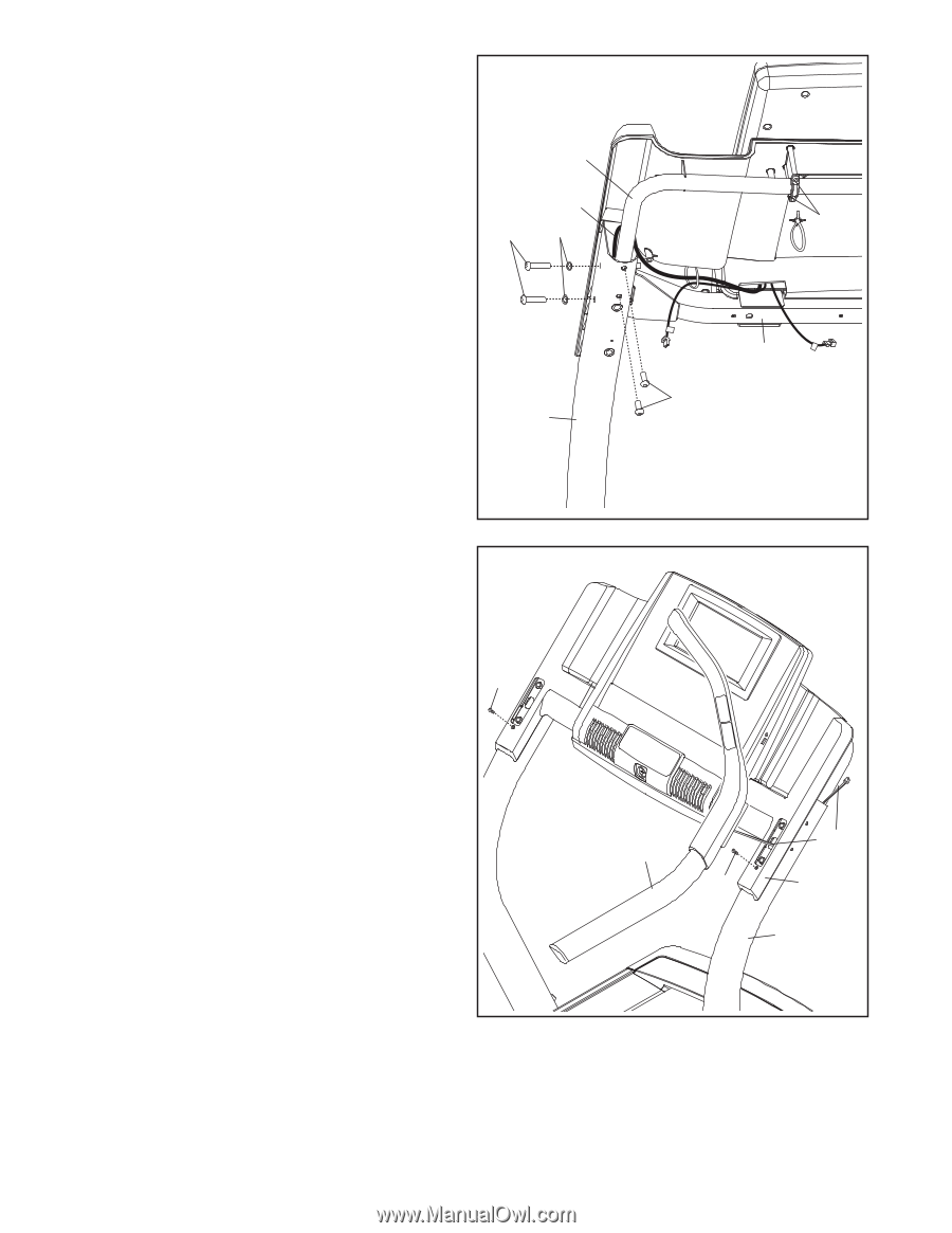
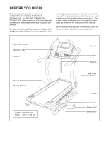
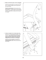
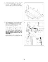
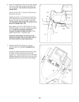
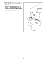
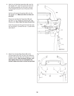
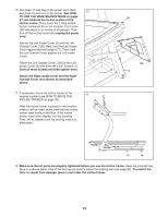
6. Insert the Upright Wire (78) into the right Upright (77) as you insert the Console Crossbar (101) into the Uprights. Be careful not to pinch the Upright Wire. Loosen the four #8 x 1" Screws (102) (only two are shown) one turn. Tighten two 5/16" x 2 1/2" Screws (4) with two 5/16" Star Washers (9) into the side of the right Upright (77) and into the Crossbar (103). Do not overtighten the Screws. Be careful not to pinch the Upright Wire (78). Next, tighten two 5/16" x 5/8" Screws (11) into the right Upright (77) and the Console Crossbar (101). It may be necessary to slide the Console Crossbar to align the holes. Then, tighten the two #8 x 1" Screws (102). Attach the left Upright (not shown) to the Console Crossbar (101) on the other side of the incline trainer as described above. 6 101 78 4 9 77 7. Tighten two #8 x 3/4" Screws (1) into the Console Base (87). Do not overtighten the 7 Screws. Identify the Right Handrail Assembly (93). Hold the Right Handrail Assembly near the right Upright (77). Insert the pulse wire from the Right Handrail Assembly into the hole in the top of the 1 Upright and pull it out of the end of the Upright. 102 R 103 11 L 93 1 Pulse Wire 87 77 12
-
 1
1 -
2
-
3
-
4
-
5
-
6
-
 7
7 -
 8
8 -
 9
9 -
 10
10 -
 11
11 -
 12
12 -
 13
13 -
 14
14 -
 15
15 -
 16
16 -
 17
17 -
18
-
19
-
20
-
21
-
22
-
23
-
24
-
25
-
26
-
27
-
28
-
29
-
30
-
31
-
32
-
33
-
34
-
35
-
36
-
37
-
38
-
39
-
40
 |
 |