NordicTrack Sl720 English Manual - Page 6
M8 x 40mm Button Screws 54 and four M8 Split
 |
View all NordicTrack Sl720 manuals
Add to My Manuals
Save this manual to your list of manuals |
Page 6 highlights
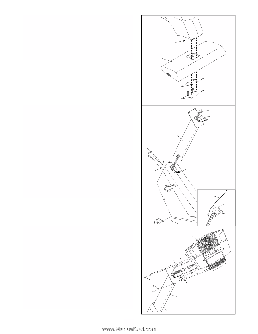
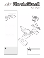
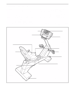
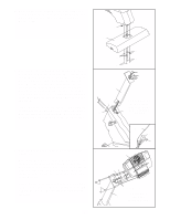
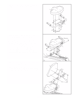
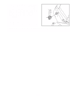
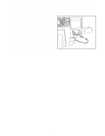
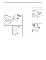
2. While another person lifts the rear of the Frame (1), attach the Rear Stabilizer (16) to the Frame with four M8 x 40mm Button Screws (54) and four M8 Split Washers (55). 2 1 16 3. Have another person hold the Upright (2) in the position shown. Refer to the inset drawing. Locate the wire extending from the bottom of the Upright. Tie the wire around the ends of the Wire Harness (43) and the Pulse Wire (3) as shown. Carefully pull the wire up through the Upright until the Wire Harness and the Pulse Wire are extending from the top of the Upright. Untie the wire and discard it. Carefully pull the ends of the Wire Harness and the Pulse Wire to remove any slack. Insert the Upright (2) into the Frame (1). Be careful to avoid pinching the Wire Harness (43) or the Pulse Wire (3). Attach the Upright with two M10 x 110mm Button Screws (78) and two M10 Split Washers (88). 55 55 54 54 3 43 3 2 78 88 88 Do not pinch the Wire Harness (43) or the Pulse 1 Wire (3) during this step. 4. Have another person hold the Console (4) near the Upright (2). Connect the Wire Harness (43) to the wire harness on the Console (4). Connect the Pulse Wire (3) to the pulse wire on the Console. Next, locate the two ground wires that are connected with a screw to the Upright (2). Connect the ground wires to the two smallest wires on the Console. Carefully insert all excess wiring down into the Upright (2). Attach the Console (4) to the Upright with four M4 x 16mm Screws (57). Be careful to avoid pinching the wires. 4 57 Wire 43 3 4 3 43 Ground Wires Do not pinch 2 the wires during this step. 6
-
 1
1 -
 2
2 -
 3
3 -
 4
4 -
 5
5 -
 6
6 -
 7
7 -
 8
8 -
 9
9 -
 10
10 -
 11
11 -
 12
12 -
13
-
14
-
15
-
16
-
17
-
18
-
19
-
20
-
21
-
22
-
23
-
24
-
25
-
26
-
27
-
28
 |
 |