NordicTrack Vertex 670 English Manual
NordicTrack Vertex 670 Manual
 |
View all NordicTrack Vertex 670 manuals
Add to My Manuals
Save this manual to your list of manuals |
NordicTrack Vertex 670 manual content summary:
- NordicTrack Vertex 670 | English Manual - Page 1
. CUSTOMER HOT LINE: 1-888-825-2588 Mon.-Fri., 6 a.m.-6 p.m. MST CAUTION Read all precautions and instructions in this manual before using this equipment. Save this manual for future reference. USER'S MANUAL Visit our website at www.nordictrack.com new products, prizes, fitness tips, and much more! - NordicTrack Vertex 670 | English Manual - Page 2
3 BEFORE YOU BEGIN 4 ASSEMBLY 5 CABLE DIAGRAM 21 ADJUSTMENTS 22 WEIGHT RESISTANCE CHART 24 TROUBLE-SHOOTING AND MAINTENANCE 25 EXERCISE GUIDELINES 26 ORDERING REPLACEMENT PARTS Back Cover LIMITED WARRANTY Back Cover Note: A PART IDENTIFICATION CHART and a PART LIST/EXPLODED DRAWING are - NordicTrack Vertex 670 | English Manual - Page 3
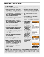
time. The weight system is designed to support a maximum user weight of 250 pounds. 8. Always wear athletic shoes for foot protection while exercising. 9. Always disconnect the lat bar from the weight system when performing an exercise that does not require it. 10. Make sure the cables remain on the - NordicTrack Vertex 670 | English Manual - Page 4
versatile NordicTrack® VERTEX 670 weight system. The VERTEX 670 offers a selection of weight stations designed to develop every major muscle group of the body. Whether your goal is to tone your body, build dramatic muscle size and strength, or improve your cardiovascular system, the VERTEX 670 will - NordicTrack Vertex 670 | English Manual - Page 5
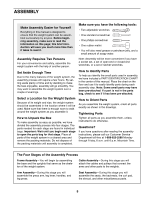
As you assemble the weight system, orient all parts exactly as shown in the drawings. Tightening Parts Tighten all parts as you assemble them, unless instructed to do otherwise. Questions? If you have questions after reading the assembly instructions, please call our Customer Service Department toll - NordicTrack Vertex 670 | English Manual - Page 6
information on page 5. This brief introduction will save you much more time than it takes to read it. 24 3 33 Open the parts bag labeled "FRAME ASSEMBLY." Press two 2" x 3" Inner Caps (24) into the ends of the Stabilizer (5). Press a 2" x 3" Inner Cap and a 2" Square Inner Cap (33) into the Main - NordicTrack Vertex 670 | English Manual - Page 7
42 4. Open the parts bag labeled "Weight Inserts." See the inset drawing. Press two Weight Inserts (77) into the indicated holes in each Weight (26). Make sure the large pin groove is oriented as shown. Slide all nineteen Weights (26) onto the Weight Guides (23). Make sure the Weights are oriented - NordicTrack Vertex 670 | English Manual - Page 8
the holes. Thread a 3/8" Nylon 50 Locknut (50) onto the lower Bolt. Do not thread a Locknut onto the upper Bolt yet. Attach the Weight Guides (23) to the Top Frame (1) with two 3/8" x 1 3/4" Bolts (60) and two 3/8" Nylon Locknuts (50). Welded Tubes 6. Press a 2" x 3" Inner Cap (24) into the - NordicTrack Vertex 670 | English Manual - Page 9
Arm Assembly 9 9. Open the parts bags labeled "ARM ASSEMBLY." Attach the Rear and Forward Leg Press Uprights (97, 98) to the Leg Press Base (84) with two 3/8" x 3 1/4" Bolts (87) and two 3/8" Nylon Locknuts (50). - NordicTrack Vertex 670 | English Manual - Page 10
13. Attach the Leg Lever Lock (11) to the front leg of 13 the Base (8) with a 5/16" x 3" Bolt (78), three 5/16" Washers (80), and a 5/16" Nylon Locknut (81). Do not overtighten the Nylon Locknut; the Leg Lever Lock must pivot easily. Front Leg 8 80 78 11 14. Press two 2" Square Inner Caps ( - NordicTrack Vertex 670 | English Manual - Page 11
Cable Assembly 16. Open the parts bags labeled "CABLE ASSEMBLY" and "4 PULLEYS." Refer to the CABLE DIAGRAM on page 21 to identify the cables and for correct cable routing. Locate the Leg Press Cable (76). Attach the Leg Press Cable to the indicated hole in the Leg Press Base (84) with a 3/8" x 3" - NordicTrack Vertex 670 | English Manual - Page 12
Stabilizer (5) with a 3/8" x 2" Bolt (62) and a 3/8" Nylon Locknut (50). Be sure that the Cable Trap (44) is positioned to hold the Cable in the pulley groove. 62 35 76 Bracket 44 5 50 21. Remove the pre-assembled 4" Pulley (not shown) 21 from the Pulley Bracket (91). Attach the end of - NordicTrack Vertex 670 | English Manual - Page 13
a 3/8" x 2 1/2" Bolt (54), two 3/8" Washers (55), two 5/8" x 1/2" Bushings (42), and a 3/8" Nylon Jamnut (63). Wrap the High Cable (73) around another 4" Pulley (35) in the direction shown. Route the High Cable through the slot in the Main Upright (3). Attach the Pulley to the Press Frame (12) with - NordicTrack Vertex 670 | English Manual - Page 14
), and a 3/8" Nylon Jamnut (63). 3 35 73 63 42 55 54 42 55 27. Disassemble the pre-assembled Pulley Plates (31). 27 Wrap the High Cable (73) around a 4" Pulley (35) in the direction shown. Attach the Pulley and a Cable Trap (44) to the top set of holes in the end of the Pulley Plates (31 - NordicTrack Vertex 670 | English Manual - Page 15
30. Route the High Cable (73) up through the next slot in the Top Frame (1) and wrap the Cable around a 4" Pulley (35) in the direction shown. Attach the Bushings (42), and a 3/8" Nylon Jamnut (63). Let the High Cable (73) hang over the weight stack; it will be attached in step 38. 31 35 1 63 - NordicTrack Vertex 670 | English Manual - Page 16
(72) through the indicated slot in the Main Upright (3) and the Base (8). Wrap the Low Cable (72) around a 4" Pulley (35) in the direction shown. Attach the Pulley inside the bracket on the Main Upright (3) with a 3/8" x 2" Bolt (62) and a 3/8" Nylon Locknut (50). 63 42 55 34 50 35 62 - NordicTrack Vertex 670 | English Manual - Page 17
into the threaded hole in the Weight Tube (36). Tighten the bolt into the Weight Tube until the Cables (73, 72, 76) are tight. Tighten the 1/2" Plain Nut (68) against the 1 1/2" Washer (40). Seat Assembly 39 39. Open the parts bag labeled "ARM AND SEAT ASSEMBLY." Attach a Seat (13) to the Seat - NordicTrack Vertex 670 | English Manual - Page 18
40. Insert a 1/4" x 3 3/4" Carriage Bolt (43) into each Backrest Plate (27). Attach the Backrest Plates to the Backrest (41) with four 1/4" x 3/4" Bolts (17). 40 71 25 17 43 41 Attach the Backrest (41) to the Main Upright (3) with the two 1/4" x 3 3/4" Carriage Bolts (43), two 1/4" Washers (71), - NordicTrack Vertex 670 | English Manual - Page 19
44. Press two 3/4" Round Inner Caps (34) into the 44 ends of the remaining Pad Tube (28). Slide the Pad Tube (28) through the hole in the Main Upright (3). Slide two Foam Pads (30) onto the ends of the Pad Tube. 30 34 30 34 28 3 45. Slide the two Tinnerman Clips (38) down over the 45 slots - NordicTrack Vertex 670 | English Manual - Page 20
parts will be explained in ADJUSTMENTS, beginning on page 22 of this manual. Before using the weight system, pull each cable a few times to make sure that the cables move smoothly over the pulleys. If one of the cables does not move smoothly, find and correct the problem. IMPORTANT: If the cables - NordicTrack Vertex 670 | English Manual - Page 21
are routed correctly, that the pulleys move smoothly, and that the cable traps do not touch or bind the cables. Incorrect cable routing can damage the weight system. 8 10 11 2 1 High Cable (73) 9 6 7 4 3 5 64 6 12 4 3 Leg Press Cable (76) Cable ID Chart 53 5 1 -76 -72 -73 21 2 2 1 Low - NordicTrack Vertex 670 | English Manual - Page 22
ADJUSTMENTS The instructions below describe how each part of the weight system can be adjusted. Refer to the exercise guide accompanying this manual to see how the weight system should be set up for each exercise. IMPORTANT: When attaching the lat bar, ankle strap, or ab strap, make sure that the - NordicTrack Vertex 670 | English Manual - Page 23
sure that the Adjustment Pins (20) are fully inserted into the same holes in both sides of the 49 Press Frame (12) before performing any exercises. 20 12 20 49 46 B 20 49 ATTACHING THE CURL PAD Remove the 2" Square Inner Cap (33) from the front leg on the Base (8). Slide - NordicTrack Vertex 670 | English Manual - Page 24
plates. Note: The actual resistance at each station may vary due to differences in individual weight plates as well as friction between the cables, pulleys, and weight guides. Weight Plates Top 1 2 3 4 5 6 7 8 9 10 11 12 13 14 15 16 17 18 19 Press Arm (lbs.) 24 35 46 57 68 79 90 102 113 124 - NordicTrack Vertex 670 | English Manual - Page 25
TROUBLE-SHOOTING AND MAINTENANCE Make sure all parts are properly tightened each time you use the weight system. Replace any worn parts immediately. The weight system can be cleaned using a damp cloth and mild non-abrasive detergent. Do not use solvents. TIGHTENING THE CABLES Woven cable, the type - NordicTrack Vertex 670 | English Manual - Page 26
time to regenerate. The combination of weight training and aerobic exercise will reshape and strengthen your body, plus exercise, and moving only the appropriate parts of the body. Exercising in an uncontrolled manner will leave you feeling exhausted. On the exercise guide accompanying this manual - NordicTrack Vertex 670 | English Manual - Page 27
and the numbers of sets and repetitions completed. Record your weight and key body measurements at the end of every month. Remember, the key to achieving the greatest results is to make exercise a regular and enjoyable part of your everyday life. MUSCLE CHART A. Sternomastoid (neck) B. Pectoralis - NordicTrack Vertex 670 | English Manual - Page 28
of the product (see the front cover of this manual) 4. The KEY NUMBER and DESCRIPTION of the part(s) (see the PART LIST and EXPLODED DRAWING in the center of this manual). LIMITED WARRANTY WHAT IS COVERED-The entire NordicTrack® VERTEX 670 weight system ("Product") is warranted to be free of all - NordicTrack Vertex 670 | English Manual - Page 29
center of this manual. Important: Some parts may have been pre-assembled for shipping. If you cannot find a part in the parts bags, check to see if it has been pre-assembled. Note: Assembly is divided into four stages: 1) frame assembly, 2) arm assembly, 3) cable assembly, and 4) seat assembly. The - NordicTrack Vertex 670 | English Manual - Page 30
1/2" x 1 3/4" Bushing (94) 1/2" x 3/4" Long Bushing (93) 5/8" x 1/4" Bushing (90) 5/8" x 1/2" Bushing (42) 3/4" Round Inner Cap (34) 1" Round Inner Cap (103) 2" Square Inner Cap (33) Cable Clip (69) 2" Round Inner Cap (57) 3/4" x 1/2" Flange Bushing (18) 2" x 3" Inner Cap (24) - NordicTrack Vertex 670 | English Manual - Page 31
3/8" x 8 1/2" Bolt (59) 3/8" x 9" Bolt (51) 3/8" x 2 1/2" Bolt (54) 5/16" x 3" Bolt (78) 3/8" x 3" Bolt (45) 3/8" x 3" Carriage Bolt (64) 3/8" x 3 1/4" Bolt (87) 1/2" x 3 1/2" Bolt (22) 3/8" x 3 3/4" Bolt (92) 1/4" x 3 3/4" Carriage Bolt (43) 3/8" x 3 3/4" Carriage Bolt (52) 3/8" x 4" Bolt (65) - NordicTrack Vertex 670 | English Manual - Page 32
PART IDENTIFICATION CHART-Model No. 831.159770 R0402A 1/4" Nylon Locknut (25) 5/16" Nylon Jamnut (79) 5/16" Nylon Locknut (81) 3/8" Nylon Jamnut (63) 3/8" Nylon Locknut (50) #8 x 3/4" Screw ( - NordicTrack Vertex 670 | English Manual - Page 33
REMOVE THIS PART LIST/EXPLODED DRAWING FROM THE MANUAL. SAVE THIS PART LIST/EXPLODED DRAWING FOR FUTURE REFERENCE 81 - NordicTrack Vertex 670 | English Manual - Page 34
Bolt Weight Cover Chain 1/2" Plain Nut Cable Clip Leg Press Backrest 1/4" Washer Low Cable High Cable Sliding Seat Frame Ab Strap Leg Press Cable Weight Insert 1" Round Inner Cap Large Washer User's Manual Note: "#" indicates a non-illustrated part. Specifications are subject to change without - NordicTrack Vertex 670 | English Manual - Page 35
23 25 17 71 55 63 42 66 73 68 40 36 47 16 93 2 32 70 17 17 53 9 101 95 33 74 101 25 17 86 95 25 17 53 17 71 17 42 35 44 33 35 15 61 18 18 51 63 102 77 26 56 32 77 39 35 42 35 42 42 55 63 55 63 63 55 50 60 42 15 1 42 35 42 35 45 54 42 55 54 50 42 55 42 55 73 54 55 14
-
 1
1 -
 2
2 -
 3
3 -
 4
4 -
 5
5 -
 6
6 -
 7
7 -
8
-
9
-
10
-
11
-
12
-
13
-
14
-
15
-
16
-
17
-
18
-
19
-
20
-
21
-
22
-
23
-
24
-
25
-
26
-
27
-
28
-
29
-
30
-
31
-
32
-
33
-
34
-
35
 |
 |

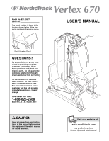
CAUTION
Read all precautions and instruc-
tions in this manual before using
this equipment. Save this manual
for future reference.
Model No. 831.159770
Serial No.
The serial number is found in the
location shown below. Write the
serial number in the space above.
Visit our website at
www.nordictrack.com
new products, prizes,
fitness tips, and much more!
USER’S MANUAL
QUESTIONS?
As a manufacturer, we are com-
mitted to providing complete
customer satisfaction. If you
have questions, or if there are
missing parts, we will guarantee
complete satisfaction through
direct assistance from our factory.
TO AVOID DELAYS, PLEASE
CALL DIRECT TO OUR TOLL-
FREE CUSTOMER HOT LINE.
The trained technicians on our
customer hot line will provide
immediate assistance, free of
charge.
CUSTOMER HOT LINE:
1-888-825-2588
Mon.–Fri., 6 a.m.–6 p.m. MST
Serial Number Decal