Olympus VN-702PC VN-702PC Detailed Instructions (English) - Page 8
Identification of parts - vn 701pc
 |
View all Olympus VN-702PC manuals
Add to My Manuals
Save this manual to your list of manuals |
Page 8 highlights
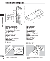
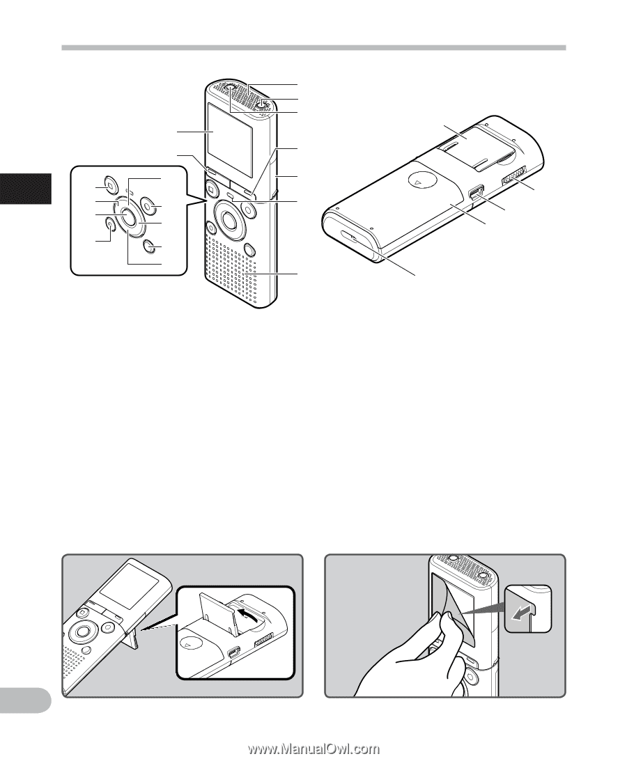
Identification of parts Identification of parts * & 1 ^ 8 % $ 9 0 # ! @ 1 2 3 ( 4 5 6 ) - = 7 q 1 Built-in microphone 2 MIC (Microphone) jack 3 EAR (Earphone) jack 4 CALENDAR/SCENE button*1 SCENE button*2 5 Card cover*1 6 LED indicator light 7 Built-in speaker 8 + button 9 REC (s) (Record) button 0 9button ! FOLDER/INDEX button @ - button # ERASE button $ `OK button % 0 button ^ STOP (4) button & MENU button * Display (LCD panel) ( Stand ) POWER/HOLD switch - USB connector = Battery cover q Strap hole *1 VN-702PC only. *2 VN-701PC only. EN • Use the stand as needed. 8 • Remove the screen protector on the display.
-
 1
1 -
2
-
 3
3 -
 4
4 -
 5
5 -
 6
6 -
 7
7 -
 8
8 -
 9
9 -
 10
10 -
 11
11 -
 12
12 -
 13
13 -
14
-
15
-
16
-
17
-
18
-
19
-
20
-
21
-
22
-
23
-
24
-
25
-
26
-
27
-
28
-
29
-
30
-
31
-
32
-
33
-
34
-
35
-
36
-
37
-
38
-
39
-
40
-
41
-
42
-
43
-
44
-
45
 |
 |
8
1
EN
3
7
6
5
4
-
)
(
=
q
*
&
^
$
#
8
9
0
!
@
%
1
2
Identification of parts
Identification of parts
1
Built-in microphone
2
MIC
(Microphone) jack
3
EAR
(Earphone) jack
4
CALENDAR/SCENE
button
*1
SCENE
button
*2
5
Card cover
*1
6
LED indicator light
7
Built-in speaker
8
+
button
9
REC
(
s
) (Record) button
0
9
button
!
FOLDER/INDEX
button
@
–
button
#
ERASE
button
$
`
OK
button
%
0
button
^
STOP
(
4
) button
&
MENU
button
*
Display (LCD panel)
(
Stand
)
POWER/HOLD
switch
-
USB connector
=
Battery cover
q
Strap hole
*1
VN-702PC only.
*2
VN-701PC only.
•
Remove the screen protector on the
display.
•
Use the stand as needed.