Panamax MOD-AT4 Manual
Panamax MOD-AT4 Manual
 |
UPC - 050616007702
View all Panamax MOD-AT4 manuals
Add to My Manuals
Save this manual to your list of manuals |
Panamax MOD-AT4 manual content summary:
- Panamax MOD-AT4 | Manual - Page 1
IN RJ-11 EQUIP OUT RJ-11 SAT / CATV SAT / CATV MOD-DBSTV 1 1 OUTSIDE LINES MOD-SPKP RECEIVER 2 2 3 3 4 4 5 5 6 6 7 7 8 8 MOD-SPKP These modules are approved accessories for use with compatible Panamax AC base units. Compatible base units include the following: Pull Out Model - Panamax MOD-AT4 | Manual - Page 2
INSTRUCTIONS FOR PANAMAX SIGNAL LINE PROTECTION MODULES - PREMIUM SERIES Model: MOD-DT4 (Secondary Protector) LINE IN RJ-45 EQUIP OUT RJ-45 WIRING DIAGRAM AND SPECIFICATIONS Bl Bl Or Or Gr Gr Br Br Pull Out MOD -11 CATV Pull Out Card The MOD-DBSTV module provides protection for 3 SAT
-
 1
1 -
 2
2
 |
 |
800-472-5555
www.panamax.com
INSTRUCTIONS FOR PANAMAX SIGNAL LINE PROTECTION MODULES - PREMIUM SERIES
When properly installed, the base unit’s
Connected Equipment Protection Policy
remains valid.
All modules include a small rectangular bracket and mounting screws.
This
bracket replaces the small triangular wall-mount bracket that comes with the models listed in
the
CURRENT PRODUCTS
above.
Module
Bracket
AC Base Unit
Ground
Connector
Ground
Connector
Ground
Connector
Pull Out Card
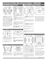
The
MOD-AT4
module is designed to pro-
tect standard phone lines and DSL (ADSL,
G.Lite) lines.
Multiple input & output jacks
provide complete installation flexibility.
The
following
diagram
shows
how
the
jacks/wires are interconnected.
Different
cables/connections can be split or com-
bined to accommodate a variety of installa-
tions.
For example:
• Incoming lines can be punched-down on
the 110 jack on the
LINE
side and four RJ11
(single-line) cords will connect from the
EQUIP
side to the equipment.
• Two RJ14 (dual-line) cords connected to
the
LINE
side (upper 2 jacks) can be split to
four RJ11 (single-line) cords on the
EQUIP
side
.
• Four RJ11 (single-line) cords connected
to the
LINE
side can be combined into a
single RJ45 (8 wire) cord (upper jack) on the
EQUIP
side.
Caution: Never install telephones
during a lightning storm.
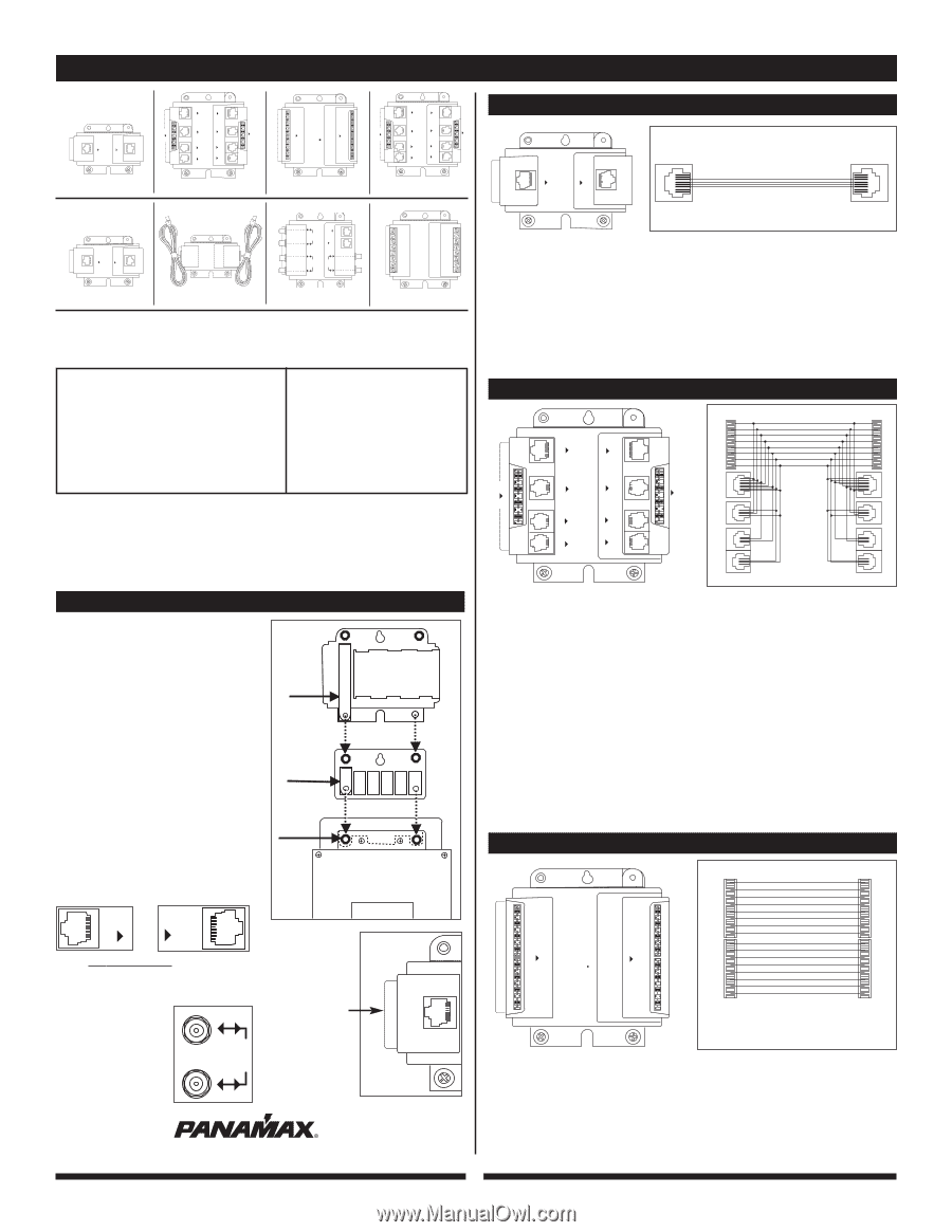
The
MOD-AT8110
module is designed to
protect up to 8 standard phone lines using
110 punchdown connectors on both the
input
LINE
and output
EQUIP
.
1.
Cut the cable from the primary protector
to the correct length and punch down the
cable to the
LINE IN
punchdown block on
the module.
2.
Punch down another cable to the
EQUIP
OUT
punchdown block on the module and
connect to the phone equipment.
MOD-AT4
EQUIP
OUT
RJ-45
LINE
IN
RJ-45
EQUIP
OUT
RJ-14
LINE
IN
RJ-14
EQUIP
OUT
RJ-11
LINE
IN
RJ-11
LINE
IN
RJ-11
EQUIP
OUT
RJ-11
EQUIP
OUT
S110D
Pull Out
LINE
IN
S110D
MOD-AT4
EQUIP
OUT
RJ-45
LINE
IN
RJ-45
EQUIP
OUT
RJ-14
LINE
IN
RJ-14
EQUIP
OUT
RJ-11
LINE
IN
RJ-11
LINE
IN
RJ-11
EQUIP
OUT
RJ-11
EQUIP
OUT
S110D
Pull Out
LINE
IN
S110D
Bl
Bl
Or
Or
Gr
Gr
Br
Br
1 - 8
1 - 4
1 - 4
1 - 4
1 - 8
1 - 4
1 - 4
1 - 4
WIRING DIAGRAM AND SPECIFICATIONS
MOD-AT4
For Analog
Telephone
Lines
• 4 Pairs (8 wires) Protected
• 260 Volt Clamping • Straight-Through Pinout
Blue
Blue
Blue
Blue
Orange
Orange
Orange
Orange
Green
Green
Green
Green
Brown
Brown
Brown
Brown
MOD-AT8110
For Analog Telephone Lines
• 16 Wires (two 110 punch-downs) Protected
• 260 Volt Clamping
• Auto-resetting PTC's
110
IDC
110
IDC
WIRING DIAGRAM AND SPECIFICATIONS
LINE
IN
S110D
EQUIP
OUT
S110D
MOD-AT8110
Pull Out
LINE
IN
S110D
EQUIP
OUT
S110D
MOD-AT8110
Pull Out
The
MOD-AT2
module is designed to protect
standard phone lines connected to computer
modems, telephones, pay-per-view ports, etc.
It will also protect DSL lines (ADSL, G.Lite)
going into the DSL modem.
The MOD-AT2
module will protect a single phone line using
an RJ-11 (2 wire) cord or a dual phone line
using an RJ-14 (4 wire) cord.
1.
Connect the telephone line to the
LINE
jack on the module.
2.
Use a modular cord to connect the
EQUIP
modular jack to the equipment to be
protected.
1 - 8
MOD-AT2
For Analog Telephone Lines
• 4 Wires (1 RJ-14) Protected
• 260 Volt Clamping
• Auto-resetting PTC's
1 - 8
WIRING DIAGRAM AND SPECIFICATIONS
MOD-AT2
EQUIP
OUT
LINE
IN
Pull Out
L
I
Pull Out
MOD-AT2
EQUIP
OUT
LINE
IN
Pull Out
SAT /
CATV
It is ver
y important
to connect
telephone signal lines properly.
1.
Mount the rectangular bracket to the back
of the AC base unit with the #8-32 x 5/16”
machine screws.
Note:
The brass ground connector must be
used with the bracket in order to bond the
module ground to the base unit’s ground.
2.
Mount the signal line module to the
bracket (screws provided with the module).
3.
Optional – The assembled base unit and
module(s) may be wall mounted if desired.
4.
Connect the wiring to the signal line
module as shown in the appropriate follow-
ing section.
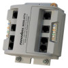
MOD-AT2
MOD-AT4
MOD-AT8110
MOD-DT4
MOD-UTP
MOD-CAT5
MOD-DBSTV
MOD-SPKP
These modules are approved accessories for use with compatible Panamax AC
base units. Compatible base units include the following:
There are no designated
input/output connections
on coaxial protection
modules. These are
bi-directional
modules
in both transmission fre-
quency and voltage.
All telephone input/output connections will
be labeled with
LINE
and
EQUIP.
Model: MOD-AT8110 (Secondary Protector)
Model: MOD-AT4 (Secondary Protector)
Installation Instructions
Model: MOD-AT2 (Secondary Protector)
MOD-DT4
EQUIP
OUT
RJ-45
LINE
IN
RJ-45
EQUIP
OUT
RJ-14
LINE
IN
RJ-14
EQUIP
OUT
RJ-11
LINE
IN
RJ-11
LINE
IN
RJ-11
EQUIP
OUT
RJ-11
EQUIP
OUT
S110D
Pull Out
LINE
IN
S110D
EQUIP.
OUT
LINE
IN
MOD-UTP
Pull Out
Pull Out
MOD-CAT5
MOD-DBSTV
E
Q
UIP
OUT
RJ-11
LINE
IN
RJ-11
SAT /
CATV
P
u
ll O
u
t
Ca
rd
SAT /
CATV
SAT /
CATV
OUTSIDE LINES
MOD-SPKP
1
2
3
4
5
6
7
8
RECEIVER
Pull Out
1
2
3
4
5
6
7
8
An easy access
PULL OUT
card
is included on
the back of each
module for wiring
diagrams and
specifications.
1
CURRENT PRODUCTS
AC Base Units
DISCONTINUED PRODUCTS
AC Base Units
PM8-EX
PM8T-EX
PM8C-EX
PM8DBS-EX
M4-EX
M4T-EX
M8-EX
M8C-EX
M8HT-PRO
M8-HT
PM8-HT
M8C-EX
M8DBS-EX
M8C-Pro
M8HC-Pro
M4
M4T
M4L
M8
M8T
M8C
M8KSU
M8COM
M8KSU
LINE
IN
EQUIP.
OUT