Panamax SP-1000 BlueBOLT Manual
Panamax SP-1000 Manual
 |
View all Panamax SP-1000 manuals
Add to My Manuals
Save this manual to your list of manuals |
Panamax SP-1000 manual content summary:
- Panamax SP-1000 | BlueBOLT Manual - Page 1
digital device in accordance with the specifications of Part 15 of FCC rules. These specifications are designed to provide reasonable the SP-1000 is within 100 ft. 6. Through the BlueBOLT interface, enable NETWORK JOINING. Refer to the user manual for BB-ZIGBEE for detailed instructions. 7. - Panamax SP-1000 | BlueBOLT Manual - Page 2
browser. 2) Follow the on screen instructions to create an account and/or take key, please follow the on-screen troubleshooting guide. Also confirm the BB-ZigBee is Panamax/Furman customer service at 1-800-472-5555. If you require technical support or equipment service, please contact the Service
-
 1
1 -
 2
2
 |
 |

SP-1000
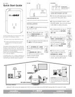
Quick Start Guide
www.panamax.com
www.mybluebolt.com
www.furmansound.com
NET.
ZIGBEE
This device complies with part 15 of the FCC Rules.
Opera-
tion is subject to the following two conditions:
(
1
) This device may not cause harmful interference, and
(
2
) This device must accept any interference received,
including interference that may cause undesired
operation.
This equipment has been tested and found to comply with
the limits for a Class B digital device in accordance with the
specifications of Part 15 of FCC rules.
These specifications
are designed to provide reasonable protection against such
interference win a residential installation.
However, there is no guarantee that interference will not
occur in a particular installation.
POWER STATUS INDICATOR LIGHTS
POWER ON/OFF and NETWORK CONNECTION STATUS INDICATORS
OUTDOOR USE IS PROHIBITED!
In accordance with FCC 15.21, changes or modifications not
expressly approved by the party responsible for compliance
could void the user’s authority to operate the equipment.
POWER / NETWORK
POWER
NETWORK
BOTTOM OUTLET
GROUND PIN RECEPTACLE
FACING WALL OUTLET
TOP VIEW
BOTTOM VIEW
INSTALLATION
1.
Turn
OFF
the equipment that you are plug-
ging into the SP-1000.
2.
Plug SP-1000 into the wall outlet.
Press the
POWER /NETWOK
button.
The blue
POWER
LED
indicates power
is on.
3.
Plug your equipment into the AC outlets and
turn
ON
your connected equipment.
4.
If the
NETWORK
LED
is
GREEN
,
the SP-1000 is connected to a ZigBee
network.
If the
NETWORK
LED
is
OFF
, the
SP-1000 is not connected to a ZigBee
network. Proceed to step
5
,
JOIN NETWORK SETUP.
5.
Verify that a BB-ZigBee Gateway is powered
on and the SP-1000 is within 100 ft.
JOIN NETWORK SETUP
6.
Through the BlueBOLT interface, enable
NETWORK JOINING.
Refer to the user manual
for BB-ZIGBEE for detailed instructions.
Multiple SP-1000 units can be installed within 100 ft. from an active ZigBee device (BB-ZIGBEE Gateway, MD2-ZB or another SP-1000).
SP-1000
SP-1000
SP-1000
7.
To indicate that the unit has not
joined the network, the
NETWORK
LED
is
OFF
.
8.
To initiate device discovery, the
POWER / JOIN NETWORK
button
is presseed for 5 seconds. While
the unit is attempting to join the
ZigBee HA network, the
NETWORK
LED
is illuminated
YELLOW
.
9.
After the unit has succesfully
joined the ZIGBee HA network, the
NETWORK
LED
is
GREEN
.
If unit fails to join the network after 10
seconds, repeat steps
5
through
9
.
BB-ZigBee Gateway
POWER
NETWORK
POWER
NETWORK
POWER / NETWORK
POWER
NETWORK
POWER
NETWORK
POWER
NETWORK
PLEASE NOTE:
The SP-1000 has two AC outlets
that are on the same circuit. Both outlets are either
On or OFF at the same time. The front side outlet
can accommodate transformer or “wall wart” types
of plugs, etc.
DQS-00009 REV. B