Panasonic 19 Touchscreen PC version Service Manual
Panasonic 19 Touchscreen PC version - Toughbook 19 Touchscreen PC Version Manual
 |
UPC - 092281896069
View all Panasonic 19 Touchscreen PC version manuals
Add to My Manuals
Save this manual to your list of manuals |
Panasonic 19 Touchscreen PC version manual content summary:
- Panasonic 19 Touchscreen PC version | Service Manual - Page 1
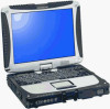
NO. CPD0711208C1 Notebook Computer Model No. CF-19FHGAXxM This is the Service Manual for the following areas. M ...for U.S.A. and Canada Model No. CF-19FHGAX 1 M 1: Operation System A: Microsoft® Windows® XP Professional J: Microsoft® Windows® VISTA Business © 2007 Matsushita Electric Industrial - Panasonic 19 Touchscreen PC version | Service Manual - Page 2
you lose the fuse cover the plug must not be used until a replacement cover is obtained. A replacement fuse cover can be purchased from your local Panasonic Dealer. IF THE FITTED MOULDED PLUG IS UNSUITABLE FOR THE SOCKET OUTLET IN YOUR HOME THEN THE FUSE SHOULD BE REMOVED AND THE PLUG CUT - Panasonic 19 Touchscreen PC version | Service Manual - Page 3
power cord to the equipment before opening the top cover of the drive. When the power switch it on, do not place your eyes close to the front panel door to look into the interior of the unit. LASER Specification Class 1 level LASER Product Wave Length: DVD 658±8 nm CD 775~815 - Panasonic 19 Touchscreen PC version | Service Manual - Page 4
After servicing, be sure to restore the lead dress, insulation barriers, insulation papers, shields, etc. Important Safety Instructions When manual. Do not dispose of batteries in a fire. They may explode. Check with local codes for possible special disposal instructions. SAVE THESE INSTRUCTIONS - Panasonic 19 Touchscreen PC version | Service Manual - Page 5
Pack) Troubleshooting Useful Use of battery packs other than those manufactured and supplied by Panasonic may present a safety hazard (generation of heat, ignition or °C to 55 °C {32 °F to 131 °F}). ( Reference Manual "Battery Power") Once the allowable range requirement is satisfied, charging - Panasonic 19 Touchscreen PC version | Service Manual - Page 6
CONTENTS 1. Specifications 2. Names and Functions of Parts 3. Block Diagram 4. Diagnosis Procedure 5. Power-On Self Test (Boot Check) 6. List of Error Codes - Panasonic 19 Touchscreen PC version | Service Manual - Page 7
(HDD) size: Run the Setup Utility ( Reference Manual "Setup Utility") and select [Information] menu. [CPU Speed]: CPU speed, [System Memory]: Memory size, [Hard Disk]: Hard disk drive size Main Specifications Model No. CPU Chipset Memory*2*4 Video Memory*1*3 Hard Disk Drive*4 CF-19FHGAXBM CF - Panasonic 19 Touchscreen PC version | Service Manual - Page 8
input "c:\util\drivers\tpm\README.pdf", and refer to the Installation Manual of "Trusted Platform Module (TPM)". *10 Only for model with ExpressCard slot *11 When using ExpressCard/34, the card slot cover cannot be closed. *12 Only for model with Smart Card slot *13 SD Memory Cards that support high - Panasonic 19 Touchscreen PC version | Service Manual - Page 9
" : Wireless WAN status Refer to the instruction manual of the wireless device. : Caps lock : Numeric key (NumLk) : Scroll lock (ScrLk) : Hard disk drive status F: Tablet Buttons Reference Manual "Tablet Buttons" G: LCD Reference - Panasonic 19 Touchscreen PC version | Service Manual - Page 10
1394 Interface Connector Reference Manual "IEEE 1394 Devices" D: Modem Port Reference Manual "Modem" E: LAN Port Reference Manual "LAN" F: SD Memory Card Indicator (Blinking: During access) Reference Manual "SD Memory Card" G: SD Memory Card Slot Reference Manual "SD Memory Card" H: Wireless Switch - Panasonic 19 Touchscreen PC version | Service Manual - Page 11
Bus 64bit 533MHz Audio Board I/O Board CRT PortRep SATA HDD 80 / 120GB 2.5" USB 2.0 x2 USB 2.0 PortRep Interface 965-GM (1.05 ) INTEL HUB Interface 1.5V BIOS SPI 8M SATA (1.5Gb/s) USB AC-link Interface DMI 533MHz AC Link Main Memory DDR2 533 1GB SO-DIMM Extension Memory DDR2 533 4GB Wireless - Panasonic 19 Touchscreen PC version | Service Manual - Page 12
4 Diagnosis Procedure 4.1. Basic Procedures - Panasonic 19 Touchscreen PC version | Service Manual - Page 13
in use. Replace keyboard or main board. Trouble symptoms on some of CD NO YES Replace main board. Check if there are any flaws on CD media. Since flaws may appear on specific media, CD media can be defective. Each kind of trouble in operation. Reinstall HDD. Replace main board. SETNADRT - Panasonic 19 Touchscreen PC version | Service Manual - Page 14
Test begins automatically when power switch is set to ON. Normal finish .....After memory checking, a beep sound is issued once and the set is placed into automatic Error message BIOS ROM error BIOS ROM error RAM error Keyboard controller error RAM error RAM error RAM error BIOS ROM error - Panasonic 19 Touchscreen PC version | Service Manual - Page 15
Following the list are explanations of the messages and remedies for reported problems. If your system displays one of except the messages marked below with an asterisk (*), write down the message and contact Panasonic Technical Support. If your system fails after you make changes in the Setup menus - Panasonic 19 Touchscreen PC version | Service Manual - Page 16
- Cache disabled Contact Panasonic Technical Support. 02F0: CPU ID: CPU socket number for Multi-Processor error. 02F4: EISA CMOS not writable ServerBIOS2 test error: Cannot write to EISA CMOS. 02F5: DMA Test Failed ServerBIOS2 test error: Cannot write to extended DMA (Direct Memory Access) registers - Panasonic 19 Touchscreen PC version | Service Manual - Page 17
BIOS password or authentication of fingerprint This key is only for entering DIAG mode. Not available to boot the computer If customer set "HDD Lock", the DIAG program cannot perform HDD test This key is for service the "Panasonic" start might become abnormal If after RAM begins from the CPU/ - Panasonic 19 Touchscreen PC version | Service Manual - Page 18
2. Operation of PC-Diagnostic Utility -Only the device which can be inspected on the entire screen is displayed. -The item does not appear when the device of wireless LAN etc. is not physically connected. -The movement of the item must use an arrow key or a flat pad. -As for the device under the - Panasonic 19 Touchscreen PC version | Service Manual - Page 19
from RAM test when the memory is increased according to the performance of the memory occasionally. çç˙ççMoreover, when the main body of PC under the test is a high temperature, it occasionally takes time. çç˙ççThere is greatly a difference from HDD according to the performance of the drive - Panasonic 19 Touchscreen PC version | Service Manual - Page 20
test Place with possibility of breakdown CPU / Main board RAM HDD MODEM Wireless LAN Sound *5 USB All memory space is tested in a special memory access pattern based on "R.S.T . technology". The record area frequently accessed with Microsoft Windows XP to test in about two minutes regardless of - Panasonic 19 Touchscreen PC version | Service Manual - Page 21
problems. The place with possibility of breakdown Main board/ Touch Screen Bluetooth cable WWAN cable FD Drive/ Main board (Super I/O)/ FDD cable FDD connector Main board (Chipset, Graphic Controller)/ Memory testing. When the test result is PASS, trouble is thought by not hearing of the sound - Panasonic 19 Touchscreen PC version | Service Manual - Page 22
CN25 CN17 CN8 CN5 CN11 CN3 COIN BATTERY MAIN PCB CN21 CN6 CN24 CN22 USB IEEE 1394 MODEM PCB CN12 SD PCB LAN PORT CN882 HDD PCMCIA UNIT POWER SW PCB CN980 CN4 DIMM CN2 CN10 DIMM CN23 CN15 LANAUX WIRELESS MODULE J1 ANT PCB PAD PCB CN801 CN804 TOUCH PAD - Panasonic 19 Touchscreen PC version | Service Manual - Page 23
. ï Shut down Windows and turn off the power. ï Disconnect the AC adaptor. ï Remove the optional DIMM memory card and PCMCIA card if they are connected. ï Remove other devices if they are connected. HDD Case B HDD FPC Hooks HDD Hooks Heater Attention: ï Please execute writing BIOS ID when you - Panasonic 19 Touchscreen PC version | Service Manual - Page 24
1 2 10. Disconnect the Cable from Connector (CN800). 11. Remove the Touch Pad and Click Button Plate. Screws : DFHE5025XA Screws : DRSB2+5FKL 9.1.4. Removing the DIMM Lid Assíy DIMM Lid Ass'y Keyboard 4. Lift the far side of the Keyboard and slide - Panasonic 19 Touchscreen PC version | Service Manual - Page 25
9.1.6. Removing the DU Lid Unit DIMM Lid Angle DU Lid Bluetooth PCB Antenna Cable(blue) HSDPA PCB Connector(CN1) Plate Clamper Connector(CN604) 1. Remove the 7 Screws . 2. Remove the DU Lid Angle and DU Lid. Screws : - Panasonic 19 Touchscreen PC version | Service Manual - Page 26
4. Remove the 2 screws , and remove the DU PCB, Plate and Antenna PCB. Connector(CN15) 5. Remove the 2 Screws , and remove the HDD Connector Guide. 6. Remove the 2 Screws. 7. Disconnect the Cable from the Connector. (CN15) 8. Remove the BAT FPC Ass'y. 9. Remove the 3 Screws. 10 - Panasonic 19 Touchscreen PC version | Service Manual - Page 27
14. Remove the 2 Screws , and remove the DIMM Holder. Tape Connector(CN9) Connector(CN14) Screws : DFHE5058ZB Screws : DRSB2+5FKL 9.1.11. Removing the Power SW PCB Connector(CN9) Power SW PCB Connector(CN23) Main PCB Combo Socket 15. - Panasonic 19 Touchscreen PC version | Service Manual - Page 28
9.1.13. Removing Pad PCB and SW PCB Pad PCB Connector(CN807) Connector(CN805) 9.1.14. Removing the Display unit LCD Hinge Cover 1. Disconnect the 2 Cables from the 2 Connectors (CN805,CN807). 2. Remove the 4 Screws . 3. Remove the Pad PCB. 1. Remove - Panasonic 19 Touchscreen PC version | Service Manual - Page 29
9.1.15. Removing the LCD Rear Case LCD Rear Case Antenna Cover Tablet Latch Cover Antenna Cover 1. Remove the 8 Screws on the - Panasonic 19 Touchscreen PC version | Service Manual - Page 30
9.1.19. Removing the Each Cover DC IN LID Rubber USB LID Rubber LAN LID Rubber Moden/LAN LID Rubber Battery LID ASS'Y HDD LID ASS'Y Audio LID Rubber USB Back Rubber RGB LID Rubber Serial LID - Panasonic 19 Touchscreen PC version | Service Manual - Page 31
9.2. Reassembly Instructions 9.2.1. Attention when CF-19 series is repaired ï Please execute writing BIOS ID when you exchange the Main Board. ï Parts (Sheet and rubber) etc. related various the Conductive Cloth and Heat Spreader cannot be recycled. Use new - Panasonic 19 Touchscreen PC version | Service Manual - Page 32
■ Assembly of LCD Back Damper (Application Model : Digitizer Model) PCB 33 35mm Attch to the side surface of the Frame. Match to the end of the Frame within 0 to 0.5 mm at the far side. Screw the Board together 0 0.5mm LCD Back Dumper Remove the Release Paper on the back side and attach it. - Panasonic 19 Touchscreen PC version | Service Manual - Page 33
■ Assembly of Inverter PCB (Applicable Model : Touch Screen Model) Inverter Ass'y Confirm the direction of the Inverter board when attaching. 30 35mm Inverter Mil Sheet Insert it between the ribs. (Fit to the Cabinet.) LCD Side Cushion E Insulation Parts Insulation Parts Avoid any stress on - Panasonic 19 Touchscreen PC version | Service Manual - Page 34
■ Assembly of Inverter PCB (Application Model : Digitizer Model) Details of cable 0 0 Inverter Ass'y LCD Back Dumper S5 Conductive Tape Attach coming over the end of steel plate by 1 to 2 mm. 0 1mm Avoid running over the rib Safety Working S2 CAUTION S1:Insulation S2:Pinching Cables S3: - Panasonic 19 Touchscreen PC version | Service Manual - Page 35
■ Assembly of Touch Screen (Applicable Model : Touch Screen Model) Touch Screen Ass'y OK (Note) Apply the load 20 to 30N (2.0 to 3.0 Kgf) to the Cushions. NG Laminate T/S Laminate Protect Sheet Attach it to the front side. (Using the jig) Dimensional tolerance: 0.2 T/S A Details of "A" Back - Panasonic 19 Touchscreen PC version | Service Manual - Page 36
■ Assembly of Glass (Applicable Model : Digitizer Model) 9.2.3. Assembling the WWAN Main Antenna PCB, LAN-Main BT Antenna PCB, LAN AUX Antenna PCB, WWAN AUX Antenna PCB and Pen holder 1. Fix the Pen Holder using the 2 Screws. 2. Attach the Pen. 3. Fix the WWAN AUX Antenna PCB using the - Panasonic 19 Touchscreen PC version | Service Manual - Page 37
■ Line Processing of Antenna Cable Safety Working CAUTION S1:Insulation S2:Pinching Cables S4:Part No. Check S5:Others S3:Sharp Edge S2 Details of "B" Avoid running over the rib, etc.. Note: Avoid any stress on the solder. Screw EVDO/EDGE Antenna S2 Details of "A" Avoid running over the rib, - Panasonic 19 Touchscreen PC version | Service Manual - Page 38
■ Assembly of LCD Hinge Initial Condition of LCD Hinge Rotation Direction S3 Cable Hold Plate Ensure the "C" side comes to the lower right corner when viewing from above. Cable Hold Plate Using the fixing jig when fixing the Hinge Fix Fix Screw LCD Hinge Safety Working Tighten S2 Avoid - Panasonic 19 Touchscreen PC version | Service Manual - Page 39
S2:Pinching Cables S4:Part No. Check S5:Others S3:Sharp Edge Step1 Cable Holder Step2 Install the Holder and Cable guide on the Hinge as shown in figure. Cable Guide HInge Cable Holder Insert the cables into the Cable Holder as shown in figure. :Position of the Antenna Cables Right - Panasonic 19 Touchscreen PC version | Service Manual - Page 40
9.2.5. Assembling the Antenna Cover, the Tablet Latch Cover and the LCD Rear Case 1. Fix the LCD Rear Case using the 10 Screws and the 2 Screws. 2. Attach the Antenna Covers and the Tablet Latch Cover to the Display Unit. 3. Tighten the 8 Screws on the back of the Display Unit. < - Panasonic 19 Touchscreen PC version | Service Manual - Page 41
■ Assembly of LCD Rear Case (Applicable Model : Touch Screen Model) (Note) Arrow without specified measurement: 0 to 0.5 mm Allowable right/left displacement of the Cushion: max. 0.5 mm Attach and apply the load 30 to 40N (3.0 to 4.0 Kgf). LCD Rear Cushion A LCD Rear Cushion A 0 0.5mm Marking - Panasonic 19 Touchscreen PC version | Service Manual - Page 42
■ Assembly of Tablet Latch Cover and Antenna Cover Press and hold it against the cabinet, Tablet Lacth Cover and fix it using the Screw. Antenna Cover Press and hold it against the cabinet, and fix it using the Screw. Screw Locations Screw 10 Places Screw 16 Places Fix in the order. the front - Panasonic 19 Touchscreen PC version | Service Manual - Page 43
9.2.6. Setting the Display Unit 1. Fix the Display Unit using the 2 Screws . 2. Close the Display Unit and turn the computer over, then fix the Display Unit using the 4 Screws . 3. Turn the computer over and fix the LCD Hinge Cover using the 2 Screws . - Panasonic 19 Touchscreen PC version | Service Manual - Page 44
■ Assembly of Display Unit Details of "A" Safety Working Note Avoid any stress on the Cable. Pass the Cable through the groove. Note: Running over affects the waterproof performance.. Black/White Blue/Gray Brown LCD UNIT Set to the Top Case Assy A LCD Cable Insert Position Order of fixing Screw - Panasonic 19 Touchscreen PC version | Service Manual - Page 45
9.2.7. Setting the Pad PCB and SW PCB 1. Attach both the SW PCB and the Operation Sheet to the Cabinet. SW PCB 2. Connect the 3 Cables to the 3 Connectors. (CN800,CN805,CN807) 3. Fix the Pad PCB using the 4 Screws. Note: Tighten the Screws in the numbered order (No1 to No4). Screws : - Panasonic 19 Touchscreen PC version | Service Manual - Page 46
■ Assembly of the Pad PCB and SW PCB (Note) Arrow without specified measurement: 0 to 0.5 mm PAD PWB ASSY PAD PWB SW FPC Insert PAD MAIN FPC ASSY No direction when inserting Back side LED(R) FPC Insert Power SW Cable Power Cable Cushion Insert Use the fixing JIG for the pressured portion - Panasonic 19 Touchscreen PC version | Service Manual - Page 47
right LED PCB LED(L) PCB Ass'y LED PCB(L) LED Light Guide Sheet(L) Match the edge and attach it. Avoid running over the N1> Screws : DFHE5025XA LED(R) PCB Ass'y Match the edge and attach it. LED Light Guide Sheet(R) LED PCB(R) LED PWB Tape(R) Match the edge and attach it. Connector(CN9) - Panasonic 19 Touchscreen PC version | Service Manual - Page 48
9.2.10. Setting the I/O PCB Ass'y 1. Fix the I/O PCB using the 2 Screws. 2. Fix the I/O PCB using the 4 Screws. Screws : DFHE5058ZB Screws : DRSB2+5FKL I/O PCB Ass'y 9.2.11. Setting the Main PCB, Wireless Module, SD PCB, DU PCB, Antenna PCB and - Panasonic 19 Touchscreen PC version | Service Manual - Page 49
, and turn 90 degrees. 11. Fix the BAT FPC Ass'y using the 2 Screws . 12. Connect the cable to the Connector. (CN15) 13. Fix the HDD Connector Guide using the 2 Screws . HDD Connector Guide Connector (CN882) SD PCB Ass'y BAT FPC Ass'y Connector(CN15) - Panasonic 19 Touchscreen PC version | Service Manual - Page 50
14. Fix the DU PCB and the Plate using the 2 screws . 15. Fix the DU PCB Ass'y and Antenna PCB using the 3 screws and the 2 screws . 16. Connect the white, black and gray Cables. DU PCB Antenna PCB Plate 17. Turn the computer over, open the - Panasonic 19 Touchscreen PC version | Service Manual - Page 51
■ Assembly of Main PCB Process in the order of 1 2 3 4. Electric wire of the cabel is not sticked out from the black tape. Tape portion can be sticked out. Do not cover the screw Fold the tape Turn over Setting the MODEM label to the line S2 Do not cover the MODEM cable and Tape to the screw - Panasonic 19 Touchscreen PC version | Service Manual - Page 52
- Panasonic 19 Touchscreen PC version | Service Manual - Page 53
Insert it before setting the Main Board. DU PCB ASSY Tape Fold back Screw Screw Screw 0 1mm Apply the lubricant (sub material) on the HDD Connector for about 1 second. Screw (Note for spraying around when applying.) Connect Main PCB Ass'y Screw Screw Round to make the brown side outside - Panasonic 19 Touchscreen PC version | Service Manual - Page 54
Thermal Rubber Screw HDD Connector Guide Screw A Screw SD PCB Ass'y Screw Screw Ensure that the knob is fit to SW when setting. DIMM HOLDER Ass'y RF SW Knob Insert the - Panasonic 19 Touchscreen PC version | Service Manual - Page 55
Ensure that both top and bottom are hooked. Screw Screw Battery FPC Ass'y Insert the end of the Sheet into the space between the Main Board and the bottom of the PCMCIA Slot. (Left and Right 0.5mm, Apply 20 to 30N (2.0 to 3.0 Kgf)) Attach it fitting to the right 0 0.5mm 0 0.5mm Slide surface - Panasonic 19 Touchscreen PC version | Service Manual - Page 56
9.2.13. Setting the HSDPA PCB and Bluetooth PCB 1. Fix the Plate and Bluetooth PCB using the 2 Screws . 2. Connect the Cable to the Connector. (CN1) 3. Connect the Cable to the Connector. (CN604) 4. Fix the Plate and the Board using the 4 Screws . 5. Attach the blue Antenna Cable to - Panasonic 19 Touchscreen PC version | Service Manual - Page 57
■ Line Processing of Antenna Cable of Main Unit Cable Process 1/3 Place brown/blue/gray cables at left and white/black cables downward. After connecting the white antenna cable, connect it into the Holder as illustrated. After connecting the black antenna cable, connect it into the Holder as - Panasonic 19 Touchscreen PC version | Service Manual - Page 58
Step 12 Connect the brown antenna cable. Step 13 Step 14 Cable Holder Cushion Insert it into the boss. (Push it downward from the top of boss.) Cable Connect the additional cable (black). Cable Process 3/3 Connect the grey antenna cable Connect the brown antenna cable Cable Holder Cushion Insert - Panasonic 19 Touchscreen PC version | Service Manual - Page 59
9.2.14. Assembling the DU Lid Unit 1. Fix the DU Lid Angle and the DU Lid using the 7 Screws. Screws : DXQT2+D25FNL DIMM Lid Angle DU Lid 9.2.15. Setting the Rear Cabinet 1. Fix the Rear Cabinet on the Computer using the 13 Screws. - Panasonic 19 Touchscreen PC version | Service Manual - Page 60
■ Cautions for Setting the Rear Cabinet (Note) Arrow without specified measurement: 0 to 0.5 mm Bottom Case Ass'y Bottom Rubber Bottom Rubber Match to the circles. 0 to 1mm Match to the wall. 0 to 1mm Match to the wall. 0 to 1mm 0 1mm Tape Potre Blind Sheet Rated Label Important Parts for - Panasonic 19 Touchscreen PC version | Service Manual - Page 61
9.2.17. Setting the Touch Pad and Keyboard 1. Connect the Cable to the Connector (CN800), and attach the Touch Pad to the computer. 2. Set the Click Button Plate. 3. Attach the new TP Tape over the Touch Pad. 4. Attach the Palm Rest Ass'y on the computer. Keyboard Keyboard FPC TP Tape 7. Set the - Panasonic 19 Touchscreen PC version | Service Manual - Page 62
■ Putting of the Sheet LCD Cushion Sheet Ensure it does not come over the end of the rib. 0 0.5mm Gasket E Ensure it does not come LCD Cushion Sheet over the end of the rib. The paste should be put the left side. Fit to the wall of the end side, and put the surplus to the Cabinet side. 0 0.5mm - Panasonic 19 Touchscreen PC version | Service Manual - Page 63
■ Putting of the Palm Rest ASSY 3 5mm 6 8mm Windows Logo Label Intel Label 5 7mm 6 8mm Energy Star Label 4 6mm Remove the Release Paper, and then attach the Palmrest Assy. Remove the two-sided tape - Panasonic 19 Touchscreen PC version | Service Manual - Page 64
9.2.18. Setting the Battery Pack and the HDD Pack 1. Set the HDD in the HDD Case and fix it using the 2 Screws. HDD Case B HDD FPC Hooks HDD Hooks Heater 2. Open the HDD Cover and set the HDD Pack. 3. Open the Battery Cover and set the Battery. Screws : DXQT2+D4FNL - Panasonic 19 Touchscreen PC version | Service Manual - Page 65
to the center 2mm Match to the level. 0 to 1 mm Attach on the inner side of the HDD Case A HDD Case Tab HDD Case Lower 0 0.5mm Screw Screw HDD Connector Guard HDD Case Upper Production HDD Damper FPC Connector Insulation Sheet Attach Remove the Release Paper Hook it Make the Hook inside - Panasonic 19 Touchscreen PC version | Service Manual - Page 66
9.2.19. Assembling the Each Cover 1. Fix the Battery LID Ass'y, the HDD LID Ass'y, and the PCMCIA LID Ass'y using the 6 Screws. < K12-16> :No.10 :No.8 :No.7 Battery LID ASS'Y HDD LID ASS'Y Audio LID Rubber USB Back Rubber RGB LID Rubber Serial LID Rubber PCMCIA LID ASS'Y - Panasonic 19 Touchscreen PC version | Service Manual - Page 67
-5 K80-7 Screw tightening torque A 0.2 +_ 0.02N m (2.0 +_ 0.2kgf cm) F 0.8 +_ 0.02N m E23 (8.0 +_ 0.2kgf cm) F N11 K5 K80-8 K80-11 K80-10 K80-8 F N11 K80 K80-1 K80-4 K80-3 K80-2 CF-19FHGAXxM - Panasonic 19 Touchscreen PC version | Service Manual - Page 68
-8 K12-13-2 A K12-13-9 K12-13-7 K12-13-1 K12-13-6 K12-13-3 B K12-13-10 K12-13-1 B K12-16 B K12-16 K12-3-5 B K12-3-10 K12-3-4 CF-19FHGAXxM - Panasonic 19 Touchscreen PC version | Service Manual - Page 69
A A N9 K126 K92 A N1 A N1 K165 A N1 E4 A N1 E406 K43 A N1 E409 E31 K42 A N1 Screw tightening torque A 0.2 +_ 0.02N m (2.0 +_ 0.2kgf cm) H 0.4 +_ 0.02N m (4.0 +_ 0.2kgf cm) CF-19FHGAXxM - Panasonic 19 Touchscreen PC version | Service Manual - Page 70
K55 K14-1-2 K16 A N10 K16 A N10 N10 A N10 A K16 A N10 A N10 K1 K14-1-1 A K14-8 A K14-8 K85 K84 N6 N6 Screw tightening torque A 0.2 +_ 0.02N m (2.0 +_ 0.2kgf cm) CF-19FHGAXxM - Panasonic 19 Touchscreen PC version | Service Manual - Page 71
D N17 K58 K67 K59 K57 K59 K59 K59 K54 K166 A N1 E15 K10-1 Screw tightening torque A 0.2 +_ 0.02N m (2.0 +_ 0.2kgf cm) D 0.8 +_ 0.08N m (8.0 +_ 0.8kgf cm) K10-1-4 E18 A N1 CF-19FHGAXxM - Panasonic 19 Touchscreen PC version | Service Manual - Page 72
E36-15 E36-3 E36-14 E36-13 K66 E36-8 E36-11 E36-12 E36-11 E36-10 K71 Screw tightening torque A 0.18 +_ 0.02N m (1.8 +_ 0.2kgf cm) CF-19FHGAXxM - Panasonic 19 Touchscreen PC version | Service Manual - Page 73
-6 Screw tightening torque B 0.2 +_ 0.02N m (2.0 _+ 0.2kgf cm) C 0.3 +_ 0.03N m (3.0 +_ 0.3kgf cm) D 0.8 +_ 0.08N m (8.0 _+ 0.8kgf cm) K11-1-6 K11-1-2 C N7 C N7 K11-9 B N15 D N16 B N15 D N16 B N15 C N7 K68 C N7 CF-19FHGAXxM - Panasonic 19 Touchscreen PC version | Service Manual - Page 74
When replacing any of these components, use only manufacturer's specified parts. CF-19FHGAXxM REF. NO and OS Main Block Unit E1 E2 E3 E4 AUX ANT LAN-MAIN BT ANT LAN AUX ANT CF-19 TS PCB UNIT WWAN COAXIAL CABLE LCD CABLE TS INVERTER HARD DISK KEYBOARD VISTA, U.S. MODEM CABLE MODEM DDR2-667 - Panasonic 19 Touchscreen PC version | Service Manual - Page 75
DFUP1589ZA DFUP1591ZA DFUP1593ZA S NCR-B/603A S CF-AA1633AM1 S K2CG3DR00003 S DFQW5088ZA S DFQW5097ZA DFJS954ZA FPC, LED RIGHT 6PIN LITHIUM ION BATTERY PACK AC ADAPTOR AC CORD OPERATING INSTRUCTIONS(CF-19MK2) MANUAL(CF-19MK2 VISTA) MODEM CABLE TOUCHPANEL CLOTH RECOVERY DVD, VISTA SHOULDER BELT ASS - Panasonic 19 Touchscreen PC version | Service Manual - Page 76
REAR CUSHION C LCD REAR CUSHION D LCD REAR CUSHION E TOUGHBOOK BADGE NEW PANASONIC BADGE TOP CASE ASS'Y TOP ELEPASS AUDIO WATERPROOF SHEET DSUB ASS'Y LID HINGE LID LATCH PLATE LID KNOB SHEET PCMCIA LID SHEET LID KNOB HDD LID LID KNOB SPRING LID KNOB SPRING PLATE SCREW SCREW SCREW SPACER SCREW SCREW - Panasonic 19 Touchscreen PC version | Service Manual - Page 77
KNOB SPRING BOTTOM CASE ASS'Y DIMM LID ASS'Y DIMM LID DIMM LID WP SHEET DU LID ANGLE DU LID WATERPROOF SHEET HDD BOTTOM SHEET DU LID BOTTOM CASE PLATE SPRING GUIDE PIN SCREW SCREW DU CON SPONGE RUBBER HOOT SERIAL LID RUBBER MODEM LID RUBBER USB LID RUBBER RGB LID RUBBER LAN - Panasonic 19 Touchscreen PC version | Service Manual - Page 78
HDD MOUNTING KIT HDD CASE UPPER HDD CASE LOWER HDD CASE TAB HDD DAMPER HDD CON SHEET HDD CONNECTOR GUARD HDD FPC UNIT INSULATION PARTS INSULATION SHEET(HDD HEATER) WLAN SHEET HEATER(HDD) SCREW ENERGY STAR LABEL WINDOWS WP SHEET LCD CUSHION SHEET TP BOTTOM TAPE HDD CASE SPACER KB CNT HOLE CUSHION TP - Panasonic 19 Touchscreen PC version | Service Manual - Page 79
+E4FKL DXYN2+J6FNL DXYN3+J10FNL DXYN3+J8FNL DXYN4+J8FNL XSB2+3FNL IO DC TUBE DIMM CUSHION ADHESIVE TAPE BAT INSULATION SHEET LCD CABLE PROTECTER CABLE GUIDE HINGE MCH SHEET COIN BAT SHEET LAN CONN HOLDER GASKET-65TSV13-1(T9)-1.9 THERMAL RUBBER CPU ICH RUBBER WATERPROOF SHEET LCD TS PWB SHEET DIMM - Panasonic 19 Touchscreen PC version | Service Manual - Page 80
for safety. When replacing any of these components use only manufacturer's specified parts. CF-19FHGAXxM REF. NO and AREA MAIN PCB C 1, 135, 136, 137, 197 522, 523, 524, 601, 607, 642, C 1604,6116,5162,61938, 14, 15, 16, 17, 18, 19, 20, 21, 22, 23, 24, 25, 26, 27, 28, 29, 30, 31, 32, 33, 34 - Panasonic 19 Touchscreen PC version | Service Manual - Page 81
C 97, 255, 256, 315, 321, F1H1A1050015 CAPACITOR, 10V, 1µF 21 336, 337, 340, 341, 342, 343, 386, 387, 389, 390, 525, 603, 726, 740, 751, 768 C 98, 99, 100, 101, 102, F1G0J474A001 CAPACITOR, 6.3V, 0.47µF 7 103, 104 C 105, 106, 107, 108, 109, F1J0J226A051 CAPACITOR, 6.3V, 22µF 9 110, - Panasonic 19 Touchscreen PC version | Service Manual - Page 82
C 766 F1G1H152A496 CAPACITOR, 50V, 1500pF 1 CF 1, 2, 3 D4CC1103A038 THERMISTOR 3 CN 2 K1MYL0B00003 CONNECTOR 1 CN 4 K1NAF0D00003 IC, TEMPERATURE CENSOR IC 1 IC 11 C0DBZYY00017 IC 1 IC 12, 19 C0DBZYY00026 IC, USB POWER SW 2 IC 14 C0DBZYY00265 POWER MANAGEMENT SWTICH 1 - Panasonic 19 Touchscreen PC version | Service Manual - Page 83
IC 1 IC 27 C2CBJA000003 IC, MICON 1 IC 30 C3FBLY000048 FLASH MEMORY 1 IC 31 C1CB00002790 IC, SECURITY CHIP 1 IC 33, 51, 26, 31, 33, B1DHDC000028 TRANSISTOR 8 630 Q 12, 14, 15, 17, 18, 19 B1MBBCA00003 TRANSISTOR 6 Q 22, 24, 36, 37, 610, 621, B1GBCFNN0042 TRANSISTOR 7 631 - Panasonic 19 Touchscreen PC version | Service Manual - Page 84
Q 611, 639, 650 B1CFGD000003 TRANSISTOR 3 Q 613, 618, 633, 636, 638, B1CFRD000014 FET 11 642, 647, 648, 652, 653, 660 Q 614, 640, 645 B1MBEDG00001 FET 3 Q 622, 627 B1CHRC000009 FET 2 Q 634, 635 B1CFRD000025 FET 2 Q 658 B1MBEDA00008 TRANSISTOR 1 R 3, 5, 20, 52, 53, 56, 192, - Panasonic 19 Touchscreen PC version | Service Manual - Page 85
R 178, 286, 704 ERJ2GEJ471X RESISTOR, 1/16W, 470Ω 3 R 181 D1HA1048A001 RESISTOR ARRAY 1 R 182 D1H81504A024 RESISTOR ARRAY 1 R 205, 206, 211 D1H84724A024 RESISTOR ARRAY 3 R 207 D1H81044A024 RESISTOR, 1/16W, 100KΩ 1 R 208, 209 ERJ2RKF4530X RESISTOR, 1/16W, 453Ω 2 R 221, 364 - Panasonic 19 Touchscreen PC version | Service Manual - Page 86
R 653, 749, 760, 777, 779, D1BDR033A099 RESISTOR, 1/3W, 0.033Ω 6 833 R 664 ERJ2GEJ684X RESISTOR, 1/16W, 680KΩ 1 R 666 ERJ2GEJ225X RESISTOR, 1/16W, 2.2MΩ 1 R 678, 682 ERJ6GEYJ122V RESISTOR, 1/10W, 1.2KΩ 2 R 679, 680 ERJ6GEYJ222V RESISTOR, 1/10W, 2.2KΩ 2 R 690 ERJ2GEJ393X - Panasonic 19 Touchscreen PC version | Service Manual - Page 87
CN 902 K1MY12BA0309 CONNECTOR 1 CN 904 K1KA02BA0014 CONNECTOR 1 D 902 B0JDBE000002 DIODE 1 F 902 S K5H202Z00005 FUSE, 2A, 32V 1 IC 900 C1CB00002733 AUDIO CODEC 1 IC 901 C0CBCBC00130 IC, REGURATOR 1 IC 902 C0JBAE000306 IC, 1 IC 903 C0JBAS000251 IC 1 IC 904 - Panasonic 19 Touchscreen PC version | Service Manual - Page 88
C 802 F1G1E103A062 CAPACITOR, 25V, 0.01µF 1 C 803, 804, 806 F1G1C104A042 CAPACITOR, 16V, 0.1µF 3 C 805 F1J0J106A016 CAPACITOR, 6.3V, 10µF 1 CN 800 K1MY04BA0104 CONNECTOR 1 CN 801 K1MY06BA0309 CONNECTOR 1 CN 802 K1MY40A00001 CONNECTOR 1 CN 803 K1MY08AA0158 CONNECTOR 1 CN - Panasonic 19 Touchscreen PC version | Service Manual - Page 89
C 619 EEFCX0J121R CAPACITOR 1 C 622 F1G1H221A495 CAPACITOR, 50V, 220pF 1 CN 600 K1MN50BA0153 CONNECTOR 1 CN 601 K1MY52BA0190 CONNECTOR 1 CN 602 K1NA08E00013 SIM CONNECTOR 1 CN 604 K1MY10BA0309 CONNECTOR 1 D 600 B0KB00000044 DIODE 1 D 603 B0JCRC000002 DIODE 1 IC 600 - Panasonic 19 Touchscreen PC version | Service Manual - Page 90
C 913, 916 F1J0J106A016 CAPACITOR, 6.3V, 10µF 2 C 914 F1G0J224A001 CAPACITOR, 6.3V, 0.22µF 1 CN 900 K1MN04B00073 CONNECTOR 1 CN 901 K1KA06BA0014 CONNECTOR 1 IC 900 C0EBE0000460 IC 1 IC 902 C1CB00002515 IC, TOUCHPANEL CONTROLLER 1 Q 900, 901 XP0431400L TRANSISTOR 2 Q 902
-
 1
1 -
 2
2 -
 3
3 -
 4
4 -
 5
5 -
 6
6 -
 7
7 -
8
-
9
-
10
-
11
-
12
-
13
-
14
-
15
-
16
-
17
-
18
-
19
-
20
-
21
-
22
-
23
-
24
-
25
-
26
-
27
-
28
-
29
-
30
-
31
-
32
-
33
-
34
-
35
-
36
-
37
-
38
-
39
-
40
-
41
-
42
-
43
-
44
-
45
-
46
-
47
-
48
-
49
-
50
-
51
-
52
-
53
-
54
-
55
-
56
-
57
-
58
-
59
-
60
-
61
-
62
-
63
-
64
-
65
-
66
-
67
-
68
-
69
-
70
-
71
-
72
-
73
-
74
-
75
-
76
-
77
-
78
-
79
-
80
-
81
-
82
-
83
-
84
-
85
-
86
-
87
-
88
-
89
-
90
 |
 |
ORDER NO.
CPD0711208C1
Notebook Computer
© 2007 Matsushita Electric Industrial Co., Ltd. All rights reserved.
Unauthorized copying and distribution is a violation of law.
CF-19FHGAXxM
Model No.
This is the Service Manual for
the following areas.
M …for U.S.A. and Canada
Model No. CF-19FHGAX
1
M
1: Operation System
A: Microsoft® Windows® XP Professional
J: Microsoft® Windows® VISTA Business