Panasonic AJ-HDX900 Dvcpro Hd Camera
Panasonic AJ-HDX900 - Camcorder - 1080i Manual
 |
UPC - 791871302781
View all Panasonic AJ-HDX900 manuals
Add to My Manuals
Save this manual to your list of manuals |
Panasonic AJ-HDX900 manual content summary:
- Panasonic AJ-HDX900 | Dvcpro Hd Camera - Page 1
Operating Instructions Camera-Recorder P Model No. AJ- E Before operating this product, please read the instructions carefully and save this manual for future use. F0706W0 -F @ Printed in Japan ENGLISH VQT0X86 - Panasonic AJ-HDX900 | Dvcpro Hd Camera - Page 2
AJ-HDX900P) CAUTION RISK OF ELECTRIC SHOCK DO NOT OPEN CAUTION: TO REDUCE THE RISK OF ELECTRIC SHOCK, DO NOT REMOVE COVER (OR BACK). NO USER SERVICEABLE PARTS INSIDE. REFER TO SERVICING TO QUALIFIED SERVICE service) instructions class A digital device, instruction manual camera-recorder in locations - Panasonic AJ-HDX900 | Dvcpro Hd Camera - Page 3
AJ-HDX900E) $ DO NOT REMOVE PANEL COVERS BY UNSCREWING THEM. To reduce the risk of electric shock, do not remove the covers. No user serviceable parts inside. Refer servicing to qualified service from a laser beam. When using the camera-recorder in locations where laser irradiation equipment is used - Panasonic AJ-HDX900 | Dvcpro Hd Camera - Page 4
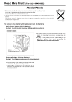
first! (For AJ-HDX900E) Attention/Attentie any other manufacturer is to be used, check the Operating Instructions accompanying the battery. O In geval u een batterij removal of the battery for disposal at the end of its service life, please consult your dealer. ORaadpleeg uw leverancier over de - Panasonic AJ-HDX900 | Dvcpro Hd Camera - Page 5
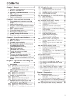
, USER1 and USER2 buttons 62 4-9-4 Setting the color temperature manually .......... 63 4-10 Set data handling 64 4-10-1 Handling the setup card 65 4-10-2 Setup card operations 65 4-10-3 How to use the user data 69 4-10-4 How to use the scene file data 70 4-10-5 Method for returning to user - Panasonic AJ-HDX900 | Dvcpro Hd Camera - Page 6
123 7-6-4 LENS FILE CARD R/W 123 7-6-5 SCENE 123 7-6-6 INITIALIZE 124 7-7 MAINTENANCE 124 7-7-1 SYSTEM CHECK 124 7-7-2 DIAGNOSTIC 124 7-7-3 LENS ADJ 124 7-7-4 BLACK SHADING 125 7-7-5 WHITE SHADING 125 7-7-6 LENS FILE ADJ 125 7-8 VTR MENU 126 7-8-1 VTR FUNCTION 126 7-8-2 BATTERY/TAPE 126 - Panasonic AJ-HDX900 | Dvcpro Hd Camera - Page 7
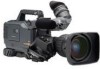
Chapter 1 General The AJ-HDX900 is a video camera-recorder that integrates an HD camera part equipped with a progressive scan (full pixel 1 reading) 3-CCD camera unit featuring a 2/3-inch on-chip lens with a VTR that in turn supports the DVCPRO HD EX format. The progressive scan CCD produces high - Panasonic AJ-HDX900 | Dvcpro Hd Camera - Page 8
of the conventional DVCPRO HD format. O PRE Unislot wireless receiver The unit's construction supports a slot-in wireless receiver, which video output can be switched between HD SDI signals and down converter output signals (serial digital video when fixing the camera on a crane. (Refer to page 89) 8 - Panasonic AJ-HDX900 | Dvcpro Hd Camera - Page 9
can easily optimize the unit's balance when the lens, battery, and other peripheral camera devices have been installed on the unit. (Refer connected viewfinder. Confirm images in multi formats by connecting the viewfinder (AJ-HVF21G), which is available as an optional accessory. (Refer to page - Panasonic AJ-HDX900 | Dvcpro Hd Camera - Page 10
Remote control unit: AJ-RC10G 2-inch electronic HD viewfinder: AJ-HVF21G (Mic holder provided) Microphone holder: AJ-MH800G Lens (Bayonet type): Fujinon, Canon GPS unit: AJ-GPS900G (This unit is not available in European region.) Rain cover: SHAN-RC700 Camera-Recorder: AJ-HDX900 Battery PROPAC14 - Panasonic AJ-HDX900 | Dvcpro Hd Camera - Page 11
problems, the power will come back on. 5 VF connector Viewfinder AJ-HVF21G (optional accessory) is connected here. Insert the connector for the viewfinder firmly until it clicks. 6 Shoulder belt fittings The shoulder belt is attached here. 7 Light shoe Use this to attach the video light, etc. 8 Lens - Panasonic AJ-HDX900 | Dvcpro Hd Camera - Page 12
for automatic adjustment. MAN : Set here for manual adjustment. 4 AUDIO IN (audio input selector recorded. When you use stereo microphone (AJ-MC900G optional), set both CH1 and CH2 to or microphones are connected here. This unit does not support AES/EBU signals. 6 LINE/MIC/+48V (line input - Panasonic AJ-HDX900 | Dvcpro Hd Camera - Page 13
an external switch to this connector. Since a tally lamp can also be used by connecting an LED to this connector, it is useful for shooting video when fixing the camera on a crane. For details, see "5-11 Connection of the external switch." 13 - Panasonic AJ-HDX900 | Dvcpro Hd Camera - Page 14
; 2 = Shooting and recording (camera unit) 1 CC FILTER/ND FILTER (filter switching) controls in accordance with the subject's brightness and color temperature. CC FILTER knob (outside, large used to select the gain of the video amplifier in accordance with the lighting conditions - Panasonic AJ-HDX900 | Dvcpro Hd Camera - Page 15
. AUTO KNEE OFF: The images shot by the camera are output. The MANUAL KNEE circuit operates. BARS: Color bar signals are output. The AUTO KNEE circuit does not operate. AUTO KNEE function When shooting with the level set to people or scenes against a highbrightness background, the background will be - Panasonic AJ-HDX900 | Dvcpro Hd Camera - Page 16
the viewfinder screen by entering HD-Y signals. D EJECT button This is pressed to insert or eject the cassette. E STOP button This is pressed to stop the tape travel. F PLAY/PAUSE button This is pressed to view the playback picture on the viewfinder screen or using a color video monitor. The button - Panasonic AJ-HDX900 | Dvcpro Hd Camera - Page 17
camera-recorder and cause malfunctioning. Always connect the DV cable to the unit with the 6-pin type DV connector first. O You can connect a digital video unit equipped with a DV connector and digitally transfer video recording device connected to the DVCPRO connector using the unit, set - Panasonic AJ-HDX900 | Dvcpro Hd Camera - Page 18
HD Y reference signal is supplied to this connector when the camera unit is to be gen-locked or the time code is to be externally locked. It is also possible to supply composite video button This causes the digit to be set to code on the tape with scene-to-scene continuity is recorded - Panasonic AJ-HDX900 | Dvcpro Hd Camera - Page 19
CTL VTCG TIME DATE P-iREC 10 h Y minM TAPE E BATT E sD frm B F RF SERVO HUMID SLACK 20 30 40 OO 13 -dB 24 Warning displays RF: Clogged video head SERVO: Servo disturbance HUMID: Formation of condensation on the head drum SLACK: Problem in tape take-up For details, refer to "6-3 Warning - Panasonic AJ-HDX900 | Dvcpro Hd Camera - Page 20
recording standby. i: Flashes when the interval recording mode has been selected. NDF SLAVE HOLD GPS OVER OVER 0 CTL VTCG TIME DATE P-iREC 10 h Y minM TAPE E BATT E sD frm B F RF SERVO HUMID SLACK 20 30 40 OO 13 -dB 24 Displays relating to the time code NDF: Lights when the time - Panasonic AJ-HDX900 | Dvcpro Hd Camera - Page 21
of the picture seen inside the viewfinder. Its adjustment does not affect the output signals of the camera. 7 Front tally lamp This lamp is activated when the TALLY switch 3 is set to the HIGH position of the viewfinder. For more information, see the instruction manual for the viewfinder. 21 - Panasonic AJ-HDX900 | Dvcpro Hd Camera - Page 22
has formed inside the unit, the HUMID display lights. Wait until this display is cleared before proceeding with the intended operation. HUMID display Checking for tape slack Gently push in the reel using your finger and turn the reel in the direction of the arrow. If the reel fails to turn - Panasonic AJ-HDX900 | Dvcpro Hd Camera - Page 23
and recording. Before actually departing to shoot scenes, carry out inspections to ensure that the If there is nothing wrong with the battery setting, replace the existing battery pack with a fully charged battery tape and close the cassette holder. ≥ Position of the accidental erasure prevent - Panasonic AJ-HDX900 | Dvcpro Hd Camera - Page 24
." 3 Point the camera at the subject, and tape. Thus, video images or voice for 2 to 3 seconds will be recorded on tape, when you start recording while the VTR SAVE/STBY switch is set to the SAVE position and then stop it immediately by pressing the REC START button or the VTR button on the lens - Panasonic AJ-HDX900 | Dvcpro Hd Camera - Page 25
> screen from the OPERATION page, and set the RET SW item to R. REVIEW. 3 When the recorded tape is replayed to the starting point of the unrecorded section, the recording head is at Position B. If the RET button of the lens or the USER button that is allocated the RET SW function is pressed - Panasonic AJ-HDX900 | Dvcpro Hd Camera - Page 26
the VTR button on the lens. If you stop recording by pressing the REC START button or the VTR button on the lens, the message "TAPE ¢S" will be displayed on VTR button on the lens. ≥ The video data and audio data are not stored in the storage memory while playback or rec-review is being performed. - Panasonic AJ-HDX900 | Dvcpro Hd Camera - Page 27
REC TIME t1 t1 t1 t1 t1 (recording time = t1) Real-time video signals Real-time audio signals 1 2 3 N-1 N PAUSE TIME t2 t2 lens once more. Interval recording is now started again. When recording is to be suspended at any time Press the STOP button. Recording is now suspended. O The tape - Panasonic AJ-HDX900 | Dvcpro Hd Camera - Page 28
is underway. Real-time video signals Real-time audio signals iREC start A t Time base What is recorded on the tape Previous cut A REC TIME (recording time = t1) When the recording is to be continued Press the unit's REC START button or VTR button on the lens once more. One-shot recording - Panasonic AJ-HDX900 | Dvcpro Hd Camera - Page 29
the HD color video monitor. ≥ In order to view these images, the OUTPUT SEL switch on the side panel must be set to the VTR position. In addition, when the FF and REW buttons are used, the images can be played back at different speeds by establishing the cue mode (PLAY + FF), review mode - Panasonic AJ-HDX900 | Dvcpro Hd Camera - Page 30
and settings for recording 4-1 Multi Format 4-1-1 Video system and Recording format The unit employs a progressive scan (full pixel reading) CCD system. It is possible to select 11 kinds of the recording formats by combinations of the SYSTEM MODE item and the CAMERA MODE item on the - Panasonic AJ-HDX900 | Dvcpro Hd Camera - Page 31
formats to be output from the respective connectors are shown below. Menu setting O Recording on tapes O HD SDI signal output (VIDEO OUT connector/MON OUT connector) SYSTEM CAMERA MODE item MODE item Video signals Audio Time code 1080-59.94i 60i 30P 60i 30P Over 60i User bits UMID - Panasonic AJ-HDX900 | Dvcpro Hd Camera - Page 32
switches as shown in the figure. CC FILTER/ND FILTER controls 4 Adjust the lens aperture. In this case, adjusting the white balance by setting the signal level of in the figure below appears when the color temperature of the subject falls below 2300 K or rises above 9900 K. The - Panasonic AJ-HDX900 | Dvcpro Hd Camera - Page 33
, contact your dealer. Messages relating to white balance adjustment Error message Meaning Recommended action COLOR TEMP. Color temperature is too Select a suitable filter. HIGH high. COLOR TEMP. Color temperature is too Select a suitable filter. LOW low. LOW LIGHT There is not enough - Panasonic AJ-HDX900 | Dvcpro Hd Camera - Page 34
When the gamma ON/OFF setting has been changed 1 Set the switches as shown in the figure. ≥Check that the lens connector has been connected and that the lens aperture is set to CLOSE. ≥While the black balance is being adjusted, the gain selector circuit is switched automatically. Flicker or - Panasonic AJ-HDX900 | Dvcpro Hd Camera - Page 35
(HALF) O For shooting images when adding effects as if taken with film Video system CAMERA MODE Shutter speed 1080-59.94i 60i 1/120 1080-29.97P 30P 1/60 1080 lines O For shooting images when adding effects to the subjects' movement Video system 1080-59.94i 1080-29.97P 1080-23.98P 1080-23. - Panasonic AJ-HDX900 | Dvcpro Hd Camera - Page 36
Chapter 4 Adjustments and settings for recording (continued) 4-3-2 Setting the shutter mode and speed The shutter speeds used in the shutter mode are set by switching the SHUTTER switch. The shutter speeds in the SYNCHRO SCAN mode can easily be changed using the SYNCHRO SCAN (+ and -) buttons on - Panasonic AJ-HDX900 | Dvcpro Hd Camera - Page 37
other hand, when it is set to MAN, the levels can be adjusted manually. The recording levels on audio tracks CH3 and CH4 can be selected using in display window NDF SLAVE HOLD GPS CTL VTCG TIME DATE P-iREC OVER 0 10 h Y minM TAPE E BATT E s D frm 20 B 30 F 40 OO 1 2 -dB Audio level meter - Panasonic AJ-HDX900 | Dvcpro Hd Camera - Page 38
be performed manually. AUTO LEVEL CH3/CH4* ON OFF Input level LINE MIC AGC ON AGC ON AGC/LIMITER OFF LIMITER ON The DVCPRO HD EX format date, time) of up to 8 digits in hexadecimal numbers, can be recorded in the sub-code area (LTC) and the VIDEO AUX area (VITC). DISPLAY switch - Panasonic AJ-HDX900 | Dvcpro Hd Camera - Page 39
recording built-in color bar signals.) O tape. It will also be overlaid with the HD SDI signals output from the MON OUT connector and VIDEO OUT connector. The active frame information (update frame information) is stored in the lowest digit of the user bits, while the frame rate information (camera - Panasonic AJ-HDX900 | Dvcpro Hd Camera - Page 40
(or LTC) ¢¢:04:24:8¢ Fixed value Checking information for the 6 digits at right. Sequence No. 24P, 24PA: 0 to 4 In all other modes: Fixed at F Tape management information ≥ Updated frame information ≥ REC START/STOP mark Camera shooting mode 60i: 600 30P: 308 24P: 248 24PA: 24C - Panasonic AJ-HDX900 | Dvcpro Hd Camera - Page 41
50 Tape management information OActive frame information OREC START/STOP mark OWhen the camera's video signals rate and time code in the 24P, 25P, 30P and 50P modes. Frame rate: 24P Over 60P (2:3) Time code frame digit Active frame 00 01 02 03 04 05 06 ••• 23 24 25 26 27 28 29 Image A A B B B - Panasonic AJ-HDX900 | Dvcpro Hd Camera - Page 42
Chapter 4 Adjustments and settings for recording (continued) 4-5-2 Setting the internal clock's date and time 1 Set the DISPLAY switch to UB. 2 Press the HOLD button to cause DATE to be displayed in the display window. 3 Set the TCG switch to SET. 4 Set the date (year/month/day) using the SHIFT - Panasonic AJ-HDX900 | Dvcpro Hd Camera - Page 43
where the time code is regenerated as the value on the tape by executing the jump function. For details, refer to "3-3 Scene-to-scene continuity." Time code when the battery is replaced The backup function works even when the battery is replaced, and the time code generator continues to operate for - Panasonic AJ-HDX900 | Dvcpro Hd Camera - Page 44
24P frame, there is a video signal delay in the camera. When recording from a device HD SDI output signals, the start position of the video gains by about 90 lines. AJ-HDX900 TC IN Settings of the TC VIDEO SYNCRO item: 1 GENLOCK IN MON OUT or VIDEO OUT TC OUT TC IN VTR etc. VIDEO IN SDI IN HD - Panasonic AJ-HDX900 | Dvcpro Hd Camera - Page 45
when several units of the camera are connected in a cascade configuration. Reference video signal Example 5: When an external AJ-HDX900 1st unit TC IN GENLOCK IN TC OUT Settings of the TC VIDEO SYNCRO item: 1 AJ-HDX900 2nd unit and later TCG TC OUT 4 AJ-HDX900 TC IN Settings of the TC VIDEO - Panasonic AJ-HDX900 | Dvcpro Hd Camera - Page 46
(n-1)-th unit Settings of the TC VIDEO SYNCRO item: 0 AJ-HDX900 n-th unit TC IN GENLOCK IN Settings of the TC VIDEO SYNCRO item: 2 TC OUT A device that synchronizes with the TC IN input and capable to record without delay (such as DAT or a camera recorder) TC IN DAT Operating procedure for - Panasonic AJ-HDX900 | Dvcpro Hd Camera - Page 47
camera unit is gen-locked by the reference video signal which is supplied to the GENLOCK IN connector. O When the signal from the unit's HD SDI connector is to be used as the reference video on the Country Codes (21) stipulated under the ISO 3166 standard. Given here as an example is the - Panasonic AJ-HDX900 | Dvcpro Hd Camera - Page 48
while a waveform monitor is used to monitor the camera's output waveforms. Video engineer support is normally required for this. The items under this lens file and other file-related operations. MAINTENANCE: This item is used to perform the maintenance and inspections related to this unit's camera - Panasonic AJ-HDX900 | Dvcpro Hd Camera - Page 49
button is pressed. **** MAIN MENU **** SYSTEM SETTING PAINT VF # OPERATION FILE MAINTENANCE VTR MENU USER MENU SELECT 3 Turn the JOG dial button to move menu screen appears when the JOG dial button is pressed. < OPERATION > CAMERA ID SHUTTER SPEED SHUTTER SELECT # USER SW SW MODE WHITE BALANCE MODE - Panasonic AJ-HDX900 | Dvcpro Hd Camera - Page 50
instructions of each viewfinder.) 1 TALLY/REC (recording) lamp This lights up (red) during recording. It flashes when a problem interrupted, replace the CAMERA ID :BAR ID POSITION :UPPER L DATE/TIME :OFF ZOOM LVL :ON COLOR TEMP :ON SYSTEM MODE :ON CAMERA MODE :ON #< VF INDICATOR2 > TAPE - Panasonic AJ-HDX900 | Dvcpro Hd Camera - Page 51
Camera mode 60i 30P 24P 24PA 50i 25P 60P 50P This indicates the video systems for recording signals output from the CCD on tape and outputting signals as HD indicates the remaining digital battery charge in percent PRE. EXTENDER BLACK GAMMA. MATRIX COLOR COR. FILTER This indicates the current - Panasonic AJ-HDX900 | Dvcpro Hd Camera - Page 52
AUDIO: channel input signals and levels) : Camera warning and message display area (Displays related ¢.¢K AWB B OK ¢.¢K AWB BREAK ¢.¢K AWB NG COLOR TEMP LOW COLOR TEMP HIGH LEVEL OVER LOW LIGHT TIME OVER AWB PRESET has been selected. This appears when the lens extender has been set to ON or OFF - Panasonic AJ-HDX900 | Dvcpro Hd Camera - Page 53
This appears when the lens extender is in use. This indicates the color temperatures assigned to problem has occurred during recording. This indicates that a problem has occurred in a mechanism. Depending on the nature of the trouble the tape has dropped. This signals that it is time to replace the - Panasonic AJ-HDX900 | Dvcpro Hd Camera - Page 54
lens cable is not connected. This appears when the lens aperture is open. This indicates the aperture value (f-value) of the lens. This appears when the lens built-in memory are recorded on tape). This appears during the jump function. This appears when the video level of a part with high brightness - Panasonic AJ-HDX900 | Dvcpro Hd Camera - Page 55
of cassette tape - 5 Remaining tape ≤ 6 Unit's REC display ≤ 7 Battery type - 8 Remaining battery charge/voltage ≤ 9 MODE CHECK dedicated display area - : Camera warning, message display area - ; Information allocated to USER buttons - < Extender ≤ = Color temperature ≤ > Filter - Panasonic AJ-HDX900 | Dvcpro Hd Camera - Page 56
ID is not displayed while the setting menu is displayed even if color bar signals are output. 1 Perform a menu operation to open the screen from the OPERATION page. #< CAMERA ID > ID1 : ABCDEFGHIJ ID2 : ABCDEFGHIJ ID3 : ABCDEFGHIJ The MKR: A indication at the upper right of - Panasonic AJ-HDX900 | Dvcpro Hd Camera - Page 57
KNEE selection switch to "BARS." The camera ID is recorded at the same time as the color bar signals if "CAMERA ID" on the VF INDICATOR screen has been set to "BAR." The camera ID is not recorded for video signals other than the color bar signal. 4-7-8 Marker check screen displays (MARKER - Panasonic AJ-HDX900 | Dvcpro Hd Camera - Page 58
; in playback mode, the VTR's playback signals are output. CAM: The camera images are output at all times. VIDEO OUT OUTPUT SEL switch Set the characters to be superimposed on the signals output from the VIDEO OUT connector by using the VIDEO OUT CHARACTER switch and the OUTPUT ITEM item on the menu - Panasonic AJ-HDX900 | Dvcpro Hd Camera - Page 59
set the size by units of 1% with a fixed ratio between of width and height. For superimposing the frame marker on the output signals from the VIDEO OUT connector. ON: To superimpose OFF: Not to superimpose For setting the frame marker. The VISTA setting is 16:8.65. For superimposing the user box - Panasonic AJ-HDX900 | Dvcpro Hd Camera - Page 60
signals. Even when the tape is replayed, images from the camera are output. Item MONI OUT Variable range Remarks HD-SDI HD-Y Set video signals output from the MON OUT connector. HD-SDI: For outputting the HD SDI signals HD-Y: For outputting the analog HD-Y signals Set the marker and user boxes - Panasonic AJ-HDX900 | Dvcpro Hd Camera - Page 61
L/M/H standard gain settings: the analog gain-up S.GAIN (super gain) mode to achieve a gain of 30 dB or more, the cumulative gain-up DS.GAIN (digital super gain) mode which uses progressive drive, and the LINE MIX GAIN mode where the gain of two lines is mixed. To select these functions - Panasonic AJ-HDX900 | Dvcpro Hd Camera - Page 62
area is allocated. RET SW: The function of the RET button on the lens is allocated. PRE REC: The function to turn ON/OFF the PRE RECORDING Since the DRS function compresses the video levels of sections with high brightness, there are slight differences in color development when the DRS function is - Panasonic AJ-HDX900 | Dvcpro Hd Camera - Page 63
A TEMP 4 item, and the AWB B TEMP item. Using the menu operation, open the screen from the OPERATION page. Even if the color temperatures are set manually, when auto adjustment of the white balance is executed in the A or B position of the WHITE BAL switch, the - Panasonic AJ-HDX900 | Dvcpro Hd Camera - Page 64
(Revision disable) No. of files: 1 SCENE WRITE SCENE READ LENS FILE READ LENS FILE WRITE SCENE file No. of files: 4 LENS file No. of files: 8 LENS FILE CARD R/W LENS FILE CARD R/W READ WRITE : Files built in the unit : Menu operations SD memory card Lens file No. of files: 8k8 It is possible - Panasonic AJ-HDX900 | Dvcpro Hd Camera - Page 65
accessory) can be used as a setup card that stores up to eight files of settings menu specifications. The setup card can be inserted or removed before or after the power is switched on. O The unit supports SD memory cards from 8 MB to 2 GB. O The SD memory card - Panasonic AJ-HDX900 | Dvcpro Hd Camera - Page 66
NG ERROR (the card cannot be formatted) The card may be defective. Replace it. CONFIG NG WRITE PROTECT Remove the card to cancel write protect. Perform the menu operations, and display the "CARD READ/WRITE" screen. Selecting the file No. 2 Turn the JOG dial button to move the arrow (cursor) to - Panasonic AJ-HDX900 | Dvcpro Hd Camera - Page 67
) WRITE NG WRITE PROTECT Insert the card. The card was formatted by a device other than the unit. Replace the card. The card may be defective. Replace it. Remove the card to cancel write protect. Selecting the file No. 2 Turn the JOG dial button to move the arrow (cursor) to the R.SELECT item and - Panasonic AJ-HDX900 | Dvcpro Hd Camera - Page 68
not been inserted) READ NG FORMAT ERROR (formatting error) The card was formatted by a device other than the unit. Replace the card. READ NG NO FILE (file not found) Save the file data. READ NG ERROR (the data cannot be loaded) Data saved by devices other than unit cannot be loaded. 7 Press - Panasonic AJ-HDX900 | Dvcpro Hd Camera - Page 69
> screen. 2 Turn the JOG dial button to move the arrow (cursor) to the READ USER DATA item. < SCENE > # READ USER DATA SCENE SEL READ :1 4 WRITE RESET TITLE1 : ******** TITLE2 : ******** TITLE3 : ******** TITLE4 : ******** 3 When the JOG dial button is pressed, the following message - Panasonic AJ-HDX900 | Dvcpro Hd Camera - Page 70
the data written can be read from this area. Up to four scene files can be registered. By using this data, the appropriate setup statuses can press the JOG dial button. The setting data is now stored in the scene file area of the unit's internal memory. 8 Press the MENU button to exit the menu operations. - Panasonic AJ-HDX900 | Dvcpro Hd Camera - Page 71
cursor) to YES, and press the JOG dial button. The data stored in the scene file area of the unit's internal memory is read, and the setting is completed. 8 YES, and press the JOG dial button. The data stored in the scene file area of the unit's internal memory is reset and the factory settings are - Panasonic AJ-HDX900 | Dvcpro Hd Camera - Page 72
: ******** 11 Turn the JOG dial button to move the arrow (cursor) to YES, and press the JOG dial button. The title is stored in the scene file area of the unit's internal memory. 12 Press the MENU button to exit the menu operations. 4 Press the JOG dial button again and turn it - Panasonic AJ-HDX900 | Dvcpro Hd Camera - Page 73
DATA saved in accordance with "4-10-3 How to use the user data," and the other method that returns without menu operations. Operation method without performing FILE menu operations 1 Set the POWER switch to the OFF position. 2 Set the WHITE BAL switch to the PRST position. It is possible to return - Panasonic AJ-HDX900 | Dvcpro Hd Camera - Page 74
"AWB" to adjust the white balance automatically. 6 Measure the signal level of RGB by using the waveform monitor (WFM). 7 Replace the lens to one where a lens file is provided. 8 Adjust the lens aperture so that the signal level of Gch is the same signal level as the one obtained in 6 above. 9 Using - Panasonic AJ-HDX900 | Dvcpro Hd Camera - Page 75
When the JOG dial button is pressed, the arrow (cursor) moves to the title input area, and the input mode is established. < LENS FILE > FILE SELECT :1 READ WRITE RESET ALL m TITLE: 1: 5: 2: 6: 4 3: 7: 4: 8: 7 Press the JOG dial button again and turn it until the character to be set - Panasonic AJ-HDX900 | Dvcpro Hd Camera - Page 76
and settings for recording (continued) 11 When the JOG dial button is pressed, the arrow (cursor) returns to the TITLE: item. < LENS FILE > FILE SELECT :1 READ WRITE RESET ALL n TITLE:222222222222 1: 5: 2: 6: 3: 7: 4: 8: 12 Turn the JOG dial button to move the arrow (cursor) to the - Panasonic AJ-HDX900 | Dvcpro Hd Camera - Page 77
bottom of the viewfinder screen. 4 4 Press the JOG dial button to enter the file number. 5 Turn the JOG dial button to move the arrow (cursor) to the READ item < LENS FILE > FILE SELECT :1 n READ WRITE RESET ALL TITLE: 1: 5: 2: 6: 3: 7: 4: 8: 6 When the JOG dial button is pressed - Panasonic AJ-HDX900 | Dvcpro Hd Camera - Page 78
2: 6: 3: 7: 4: 8: 6 When the JOG dial button is pressed, the arrow (cursor) moves to the title input area, and the input mode is established. A total of 64 lens files (8 lens files k 8 titles) can be saved on an SD memory card. Now perform step 7 on page 75 through step 15 on page 76. 78 - Panasonic AJ-HDX900 | Dvcpro Hd Camera - Page 79
shown on this screen. To display these titles, load the files, and check the titles on the LENS FILE screen. The lens files in the unit's internal memory will be rewritten as the loaded lens files at this time. For this reason, save the lens files in the internal memory onto the SD memory card first - Panasonic AJ-HDX900 | Dvcpro Hd Camera - Page 80
change it in the BATTERY SELECT item. #< BATTERY/TAPE > BATTERY SELECT :DIONIC EXT DC IN SELECT : > ≥Batteries of other makes can also be supported by changing the setting menu but no guarantees the recharging method, refer to the operating instructions of the battery concerned.) Release lever - Panasonic AJ-HDX900 | Dvcpro Hd Camera - Page 81
servicing instructions are for use by qualified service personel only. To reduce the risk of electric shock, do not perform any servicing other than that contained in the operaiting instructions menu item. This item is selected from the screen on the VTR FUNCTION page. When using - Panasonic AJ-HDX900 | Dvcpro Hd Camera - Page 82
Chapter 5 Preparation (continued) 5-1-2 Use of the external DC power supply 1 Connect the external DC power supply to the DC IN socket on the unit. DC IN socket External DC power supply 2 Turn "ON" the power switch of the external DC power supply. (If the power switch is available on the external - Panasonic AJ-HDX900 | Dvcpro Hd Camera - Page 83
unless the lens is replaced. For details on the adjustment method and lens positions, refer also to the operating instructions that accompany the lens. 1 Attach the lens to the camera. At this stage, do not forget to connect the lens cable. 5 2 Set the lens aperture to manual and open - Panasonic AJ-HDX900 | Dvcpro Hd Camera - Page 84
that is inherent to lenses and optical systems and is therefore not indicative of a failure or malfunctioning. 1 Attach the lens to the camera. At this stage, do not forget to connect the lens cable. 2 Set the electronic shutter to OFF and the gain to "L (0 dB)." 3 If the extender is attached to - Panasonic AJ-HDX900 | Dvcpro Hd Camera - Page 85
is provided and the other when it is not provided-are stored in the unit as the data of one lens file. When making the white shading correction, make the adjustment while observing the R, G, and B waveforms in the horizontal and vertical directions with the waveform monitor. This - Panasonic AJ-HDX900 | Dvcpro Hd Camera - Page 86
, insert the wireless receiver, and screw it down. The microphone of the AJ-MC900G mic kit (optional accessory) can be attached to the viewfinder. 1 Open screw 3 Connect the microphone's connecting cable to the MIC IN jack on the camera. MIC IN jack 4 Set the AUDIO IN switch or switches to "FRONT" - Panasonic AJ-HDX900 | Dvcpro Hd Camera - Page 87
Chapter 5 Preparation (continued) 5-4-3 When using an audio component 5-5 Mounting the unit on a tripod 1 Connect the AUDIO IN connectors on the camera with the audio component using the XLR cable. 2 Set the AUDIO IN switch or switches for the channel or channels to which the audio component - Panasonic AJ-HDX900 | Dvcpro Hd Camera - Page 88
Chapter 5 Preparation (continued) 5-6 Attaching the shoulder belt Shoulder belt 5-8 Attaching the rain cover Example showing use of the SHAN-RC700 rain cover The tab opens when it is pressed. Tighten the cord. To disengage the shoulder belt, press the tabs. Check that the shoulder belt is - Panasonic AJ-HDX900 | Dvcpro Hd Camera - Page 89
or removed, ensure that the POWER switches on both the main unit and AJ-RC10G are turned "OFF". It is possible to draw 1.5 A current from an LED to this connector, it is useful for shooting video when fixing the camera on a crane. 5 DC OUT connector 41 32 Connector at lens 4: +12V 89 - Panasonic AJ-HDX900 | Dvcpro Hd Camera - Page 90
color video monitor be used to check the images. 6-1-2 Inspecting the camera unit replace the battery with one having an adequate charge. 1 2 Set the zoom to the manual zoom mode, and check its operations in this mode. Turn the manual gain setting. 7 When a lens with an extender has been installed, set the - Panasonic AJ-HDX900 | Dvcpro Hd Camera - Page 91
REC START button again. Check that the tape stops and the REC lamp inside the viewfinder goes off. 7 Use the lens VTR button to check the same operations as and CH2 reflect the changes in the strength of the sound. 3. Manual audio level adjustment function inspection 1 Set the AUDIO IN CH1 and CH2 - Panasonic AJ-HDX900 | Dvcpro Hd Camera - Page 92
color video monitor is not available. Perform menu operations to open the from the MAINTENANCE page. Check the camera output level setting under the COLOR CHECK item. #< SYSTEM CHECK > COLOR on the counter display changes irrespective of the tape travel. 7 Set the DISPLAY switch to UB - Panasonic AJ-HDX900 | Dvcpro Hd Camera - Page 93
with your dealer, and replace the spent battery with a new battery (CR2032). 6 6-2-2 Head cleaning Use the AJ-CL12MP cleaning cassette if the heads need to be cleaned. Take care to read the instructions accompanying the cleaning tape since the video heads may be damaged if the tape is not used in - Panasonic AJ-HDX900 | Dvcpro Hd Camera - Page 94
Chapter 6 Maintenance and inspections (continued) 6-2-6 Connectors and signals DC IN 1 GND 2 NC 3 NC 4 +12V Matsushita part number K1AA104H0038 Maker part number HA16RX-4P (SW1) (Hirose Denki) 4 3 2 1 AUDIO IN 1 GND 2 AUDIO IN(H) 3 AUDIO IN(C) Matsushita part number K1AB103A0007 Maker part - Panasonic AJ-HDX900 | Dvcpro Hd Camera - Page 95
from the camera to the remote control (H) Matsushita part Video signals output to the remote control GND of the video signals to the remote control Not used 8 1 7 10 9 2 6 5 3 4 DC +12 V power supply (AJ-RC10G: Max. 0.75 A) GND 6 DC +12 V power supply (AJ-HVF21G LENS should not exceed 2.5 A. 95 - Panasonic AJ-HDX900 | Dvcpro Hd Camera - Page 96
Chapter 6 Maintenance and inspections (continued) LENS 1 RET-SW 2 REC-START/STOP ON/OFF of the return video RETURN ON: GND RETURN OFF: VCC 6 GPS GND Transmission data from the GPS unit to the camera Transmission data from the camera to the GPS unit Backup power supply connector for the GPS unit - Panasonic AJ-HDX900 | Dvcpro Hd Camera - Page 97
Not used 15 CH-2 HOT Not used 16 CH-2 COLD Not used 17 +5.6V Power supply to the wireless receiver 18 VIDEO OUT Not used 19 VIDEO RET Not used 20 VIDEO EN Not used 21 RM 1 (RM CLK) Not used 22 RM 2 (RM DATA) Not used 23 RM 3 (RM WR) Not used - Panasonic AJ-HDX900 | Dvcpro Hd Camera - Page 98
a second (for at least 3 seconds during recording). Problem with the recording control signal. Recording continues but the signals may not be recorded correctly while the warning remains displayed. Rewind the tape or replace the cassette tape. 5. HUMID Indications on LCD screen WARNING lamp Tally - Panasonic AJ-HDX900 | Dvcpro Hd Camera - Page 99
recording). The video heads have become clogged. There is a problem in the video system. Replace the battery when it becomes necessary. 10. TAPE NEAR DVCPRO connector. Operation continues, but something is wrong with the signals supplied to the DVCPRO connector. Check the IEEE 1394 cable and DVCPRO - Panasonic AJ-HDX900 | Dvcpro Hd Camera - Page 100
problem Supply reel problem Take-up reel problem Capstan problem Cylinder problem Loading problem Servo transmission problem Camera transmission problem Reference signal problem Video initialization problem System format problem O Turn the power supply on again. Something is wrong with the DVCPRO - Panasonic AJ-HDX900 | Dvcpro Hd Camera - Page 101
CHECK IND !LED CARD READ/WRITE CARD R/W SELECT LENS FILE LENS FILE CARD R/W SCENE INITIALIZE VTR FUNCTION BATTERY/TAPE BATTERY SETTING1 BATTERY SETTING2 MIC/AUDIO 1 MIC/AUDIO 2 TC/UB UMID SET/INFO VTR DIAG ≥ There is a total of 42 camera-related items on three pages (14 items per page - Panasonic AJ-HDX900 | Dvcpro Hd Camera - Page 102
For AJ-HDX900E For AJ-HDX900P CUF CAMERA MODE For AJ-HDX900E For AJ-HDX900P Variable range guide for the recording time. It is impossible to record for a period longer than the recording time of the tape lens. ON: The PRE RECORDING function is activated. For details, refer to "3-4 To record video - Panasonic AJ-HDX900 | Dvcpro Hd Camera - Page 103
." For superimposing characters on the HD SDI output signals from the MON OUT connector. ON: To superimpose OFF: Not to superimpose This does not link with the VIDEO OUT CHARACTER switch. For switching the signals output from the MON OUT connector. CAM: The camera images are output at all - Panasonic AJ-HDX900 | Dvcpro Hd Camera - Page 104
VISTA setting is 16:8.65. For superimposing the user box on the HD SDI output signals from the MON OUT connector. ON: To superimpose OFF SAFETY AERA item and the FRM SIG item are interlinked with the respective connectors of VIDEO OUT, MON OUT, and REMOTE. O Settings in the respective items of USER - Panasonic AJ-HDX900 | Dvcpro Hd Camera - Page 105
colors are not reduced. CUFR SET UP For AJ-HDX900E 0% For AJ-HDX900P 7.5% CUFR For setting the setup level for the down converter output signals. When the system frequency is set to 50 Hz, the setup level will be 0%. Item Variable range Remarks GENLOCK INT EXT CUFR GL PHASE HD - Panasonic AJ-HDX900 | Dvcpro Hd Camera - Page 106
externally connected devices For setting the input channel of signals output from the DVCPRO connector. 0 - 63: To fix to the designated value AUTO: To to the HD SDI signals. ON: To output OFF: Not to output For setting that the detection signals of the communication error is output to the HD SDI - Panasonic AJ-HDX900 | Dvcpro Hd Camera - Page 107
"0". For adjusting the flare level of the Rch. Adjustment values in this item are added to the flare adjustment value that is adjusted on 7-7-6 screen. O If the remote control unit is connected, settings made from the menu are disabled. (The set value is displayed.) For adjusting the - Panasonic AJ-HDX900 | Dvcpro Hd Camera - Page 108
For performing the linear matrix adjustment. (blue/red) For performing the linear matrix adjustment. (blue/green) For selecting the color correction table when the GAIN switch is in the L position. For selecting the color correction table when the GAIN switch is in the M position. For selecting the - Panasonic AJ-HDX900 | Dvcpro Hd Camera - Page 109
(PHASE) -63 : +00 : +63 SCUFR G-Yl (PHASE) -63 : +00 : +63 SCUFR Yl (PHASE) -63 : +00 : +63 SCUFR Yl-R (PHASE) -63 : +00 : +63 SCUFR ∫ COLOR ON CORRECT OFF SCUFR Remarks For performing the hue correction for red. For performing the hue correction between red and magenta. For - Panasonic AJ-HDX900 | Dvcpro Hd Camera - Page 110
00 : 18 : 31 SCUFR LEVEL DEPEND. 0 : 3 : 5 SCUFR MASTER GAMMA 0.30 : 0.55 : 0.75 SCUFR BLACK GAMMA -3 : OFF : +3 SCUFR ∫ MATRIX TABLE OFF A S CU F RB ∫ COLOR ON CORRECT OFF S UFR Remarks For setting the master gain to -3, 0, 3, 6, 9, 12, 15, 18, 21, 24, 27 or 30 dB. For performing the - Panasonic AJ-HDX900 | Dvcpro Hd Camera - Page 111
recording format is set to 720P. H.DTL LINE MIX 0H 1H 2H SCUFR For setting the number of scanning lines to be added to the video signals in order to generate the horizontal detail signals. MASTER DTL -31 : +00 : +31 SCUFR For revising the master detail level. The underlining in the - Panasonic AJ-HDX900 | Dvcpro Hd Camera - Page 112
the zebra pattern in the skin tone area output from the VIDEO OUT connector. O When the VIDEO OUT switch is set to the SD SDI or VBS position, selecting the skin tone table for enabling the skin tone details. For fetching the color information of A or B, which is selected in the SKIN TONE TABLE item - Panasonic AJ-HDX900 | Dvcpro Hd Camera - Page 113
expressed better than when FILM LIKE2 is selected. FILM LIKE1 SD FILM LIKE3 FILM LIKE2 HD Luminance O When the GAMMA MODE SEL item is used for FILM LIKE3, the following settings are recommended. MANUAL KNEE: ON KNEE POINT : 85.0% KNEE SLOPE : 50 The underlining in the variable range column - Panasonic AJ-HDX900 | Dvcpro Hd Camera - Page 114
Chapter 7 Menu description tables (continued) 7-3-12 ∫ CAMERA SETTING Item Variable range Remarks DETAIL ON S C U F R OFF HIGH COLOR ON S C U F R OFF GAMMA ON S C U F R OFF TEST SAW ON S C U F R OFF FLARE ON S C U F R OFF H-F COMPE. ON S C U F R OFF For switching ON/OFF of the - Panasonic AJ-HDX900 | Dvcpro Hd Camera - Page 115
% : 109% CUFR For setting the ZEBRA1 detection level (IRE level). Video level 109% Zebra pattern display ZEBRA 2 ON OFF SPOT ZEBRA2 DETECT 0% ON or OFF for ZEBRA2 or selecting SPOT. For setting how much lower the camera's input light quantity should be in order for "LOW LIGHT" to be displayed - Panasonic AJ-HDX900 | Dvcpro Hd Camera - Page 116
Chapter 7 Menu description tables (continued) 7-4-2 VF MARKER 7-4-3 VF USER BOX Item Variable range Remarks TABLE A B CUFR CENTER MARK OFF 1 2 3 4 CUFR SAFETY MARK OFF 1 2 For selecting the VF MARKER setting table. This item is used to set the current values of table A or B which have been - Panasonic AJ-HDX900 | Dvcpro Hd Camera - Page 117
ON OFF CUFR ZOOM LVL ON C U F R OFF COLOR TEMP ON C U F R OFF SYSTEM MODE ON OFF CUFR CAMERA MODE ON OFF CUFR DRS ON OFF CUFR Remarks For selecting ON at any time. For setting the operation of the SAVE lamp. SAVE&TAPE: The lamp lights up when the VTR SAVE/STBY switch has been set - Panasonic AJ-HDX900 | Dvcpro Hd Camera - Page 118
EXTENDER ON OFF CUFR B.GAMMA ON OFF CUFR MATRIX ON OFF CUFR COLOR ON CORRECTION OFF CUFR FILTER ON OFF CUFR Remarks For the setting to For the setting to turn the lamp on the viewfinder on when the lens extender is activated. For the setting to turn the lamp on the viewfinder - Panasonic AJ-HDX900 | Dvcpro Hd Camera - Page 119
Chapter 7 Menu description tables (continued) 7-5 OPERATION 7-5-1 CAMERA ID 7-5-3 SHUTTER SELECT Item Variable range Remarks ID1: ********** CAMERA ID setting 1 CUF ID2: ********** CAMERA ID setting 2 CUF ID3: ********** CAMERA ID setting 3 CUF If READ FACTORY DATA is selected - Panasonic AJ-HDX900 | Dvcpro Hd Camera - Page 120
Chapter 7 Menu description tables (continued) 7-5-4 USER SW Item POSITION4 SEL For 59.94 Hz Variable range Remarks 1/100 1/120 1/250 1/500 1/1000 1/2000 HALF For setting the shutter speed for POSITION 4. For 50 Hz 1/60 1/120 1/250 1/500 1/1000 1/2000 C U F R HALF POSITION5 SEL For 59. - Panasonic AJ-HDX900 | Dvcpro Hd Camera - Page 121
COLOR BARS For AJ-HDX900P For AJ-HDX900E SMPTE FULL BARS SPLIT ARIB CUFR S.GAIN OFF L/M/H S.GAIN CUF DS.GAIN OFF L/M/H DS.GAIN CUF Remarks For setting the function when the USER button on the unit, to which the RET button of the lens or the RET SW function is allocated, is pressed. R.REVIEW - Panasonic AJ-HDX900 | Dvcpro Hd Camera - Page 122
A.IRIS WINDOW NORM1 NORM2 CENTR CUFR S.IRIS LEVEL 000 : 080 : 100 CUFR IRIS GAIN CAM LENS CUFR IRIS GAIN VALUE 01 : 10 : C U F R 20 Remarks For setting the AUTO camera or the lens. For a lens with an extender (k2, k0.8 etc.) that was manufactured before the DIGI POWER type lens - Panasonic AJ-HDX900 | Dvcpro Hd Camera - Page 123
item and the CAMERA MODE item) lens file. TITLE1 - 8: ************ For setting a title consisting of not more than 12 characters. 7-6-5 SCENE Item READ USER DATA Variable range Remarks For reading the data from the memory's user area. SCENE SEL 1 : F4 READ For selecting the scene file - Panasonic AJ-HDX900 | Dvcpro Hd Camera - Page 124
O User data O Scene file Data not returned to factory settings O Lens file O Black shading O White shading The menu data that is inherent to the user are saved in user data memory on the unit. Item COLOR CHECK Variable range ON OFF Remarks For checking whether the camera unit operates properly - Panasonic AJ-HDX900 | Dvcpro Hd Camera - Page 125
description tables (continued) 7-7-4 BLACK SHADING 7-7-6 LENS FILE ADJ Item Variable range CORRECT ON C U F R OFF DETECTION - (DIG) Remarks For selecting ON or OFF for the digital black shading compensation. For executing the digital black shading compensation. 7-7-5 WHITE SHADING Item - Panasonic AJ-HDX900 | Dvcpro Hd Camera - Page 126
tape REVIEW: The rec-review operation is performed. RETAKE: The retake operation is performed, after which playback is initiated automatically. For selecting the DVCPRO video images that may occur at dark parts on the video images can be suppressed in this mode. Distortion of compressed video digital - Panasonic AJ-HDX900 | Dvcpro Hd Camera - Page 127
. For selecting the voltage at which the battery charge is to be considered nearly depleted in 0.1 V steps when MANUAL has been selected as the setting for the menu item above. O When the digital battery is attached in the unit, the remaining capacity of the battery is displayed in percent. Item - Panasonic AJ-HDX900 | Dvcpro Hd Camera - Page 128
. 2 : The selection is enabled. / : The selection is disabled. AUTO MANUAL 11.0 : 13.2 : 15.0 For selecting how the voltage at which the at which the battery charge is to be considered depleted. O When the digital battery is attached in the unit, the remaining capacity of the battery is - Panasonic AJ-HDX900 | Dvcpro Hd Camera - Page 129
CUF REAR MIC CH2 LVL -50dB -60dB CUF REAR LINE IN LVL -3dB For AJ-HDX900E 0dB For AJ-HDX900P +4dB CUF AUDIO OUT LVL -3dB For AJ-HDX900E 0dB For AJ-HDX900P +4dB CUF HEADROOM For AJ-HDX900E 18dB For AJ-HDX900P 20dB CUF WIRELESS WARN ON OFF CUF Remarks For selecting the phantom power supply for - Panasonic AJ-HDX900 | Dvcpro Hd Camera - Page 130
video images. For details, refer to "4-5-4 Externally locking the time code". For selecting whether the time code is regenerated to the value on the tape or not, when subsequent recording starts after setting the RET SW item on the SW MODE screen to R.REVIEW and pressing the RET button on the lens - Panasonic AJ-HDX900 | Dvcpro Hd Camera - Page 131
OPERATION DRUM RUNNING color elements of the video signals are eliminated. 7 For setting the users bits to record when the video system is set to 24P or 24PA, or when the recording format is set to 720P. FRAME RATE: For recording the shooting information (frame rate etc.) of the camera - Panasonic AJ-HDX900 | Dvcpro Hd Camera - Page 132
inchesa13 inches) Weight: Approx. 4.5 kg (9.9 lb) (main unit only) [CAMERA UNIT] Image Video signal-to-noise ratio: 54 dB (typical) Registration error: Less than 0.03% (entire area, excluding lens distortion) [VTR UNIT] Tape Transport System Tape to be used: M cassette tape for 1/4-inch DVCPRO Tape - Panasonic AJ-HDX900 | Dvcpro Hd Camera - Page 133
supports the viewfinder that can be switched between 59.94 Hz and 50 Hz. DVCPRO output connector (6 pins) GPS (6 pins, connector used for AJ level: For AJ-HDX900P: +4 dBu For AJ-HDX900E: 0 dBu (-3 dBu, 0 dBu or +4 dBu, selected on menu) PHONES: Stereo mini jacks a2 Video Input Connector GENLOCK - Panasonic AJ-HDX900 | Dvcpro Hd Camera - Page 134
new product. Disposing of this product correctly will help to save valuable resources and prevent any potential negative 4881 TECHNICAL SUPPORT: Emergency 24 Hour Service (800) 222-0741 Panasonic Canada Inc. 5770 Ambler Drive, Mississauga, Ontario L4W 2T3 (905) 624-5010 Panasonic de Mexico
-
 1
1 -
 2
2 -
 3
3 -
 4
4 -
 5
5 -
 6
6 -
 7
7 -
8
-
9
-
10
-
11
-
12
-
13
-
14
-
15
-
16
-
17
-
18
-
19
-
20
-
21
-
22
-
23
-
24
-
25
-
26
-
27
-
28
-
29
-
30
-
31
-
32
-
33
-
34
-
35
-
36
-
37
-
38
-
39
-
40
-
41
-
42
-
43
-
44
-
45
-
46
-
47
-
48
-
49
-
50
-
51
-
52
-
53
-
54
-
55
-
56
-
57
-
58
-
59
-
60
-
61
-
62
-
63
-
64
-
65
-
66
-
67
-
68
-
69
-
70
-
71
-
72
-
73
-
74
-
75
-
76
-
77
-
78
-
79
-
80
-
81
-
82
-
83
-
84
-
85
-
86
-
87
-
88
-
89
-
90
-
91
-
92
-
93
-
94
-
95
-
96
-
97
-
98
-
99
-
100
-
101
-
102
-
103
-
104
-
105
-
106
-
107
-
108
-
109
-
110
-
111
-
112
-
113
-
114
-
115
-
116
-
117
-
118
-
119
-
120
-
121
-
122
-
123
-
124
-
125
-
126
-
127
-
128
-
129
-
130
-
131
-
132
-
133
-
134
 |
 |

Operating Instructions
Camera-Recorder
Before operating this product, please read the instructions carefully and save this manual for future use.
P
Model No.
AJ-
E
VQT0X86
F0706W0 -F
@
Printed in Japan
ENGLISH