Panasonic BB-HCM715A Installation Guide
Panasonic BB-HCM715A - POE Pan/Tilt Indoor Network Camera Manual
 |
UPC - 037988845606
View all Panasonic BB-HCM715A manuals
Add to My Manuals
Save this manual to your list of manuals |
Panasonic BB-HCM715A manual content summary:
- Panasonic BB-HCM715A | Installation Guide - Page 1
Guide Network Camera (PoE Ready) Model No. BB-HCM715 BB-HCM735 Please read this document before using the product, and save this document for future reference. Panasonic Network Camera Website: http://panasonic.net/pcc/ipcam/ Indoor Use Only Outdoor Ready This manual is written for both the BB - Panasonic BB-HCM715A | Installation Guide - Page 2
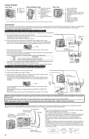
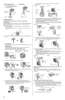
router. • Confirm that the indicator lights green after about 1 minute. If the indicator does not light green, see 1.2 Camera Indicator Issues in the Troubleshooting Guide on the CD-ROM. PoE indicator To the power supply PoE hub Green • When the lens pans or tilts, a sound can be heard from the - Panasonic BB-HCM715A | Installation Guide - Page 3
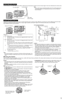
Instructions on the CD-ROM). • This terminal is an open collector circuit. The maximum drawing current is the same as terminal 4. Do not exceed the voltage of the terminal 4. DC power secure connections. • For BB-HCM715: To suit the area in which you will install the camera, you can attach the - Panasonic BB-HCM715A | Installation Guide - Page 4
). • Make sure you attach the safety wire when mounting the camera, to prevent the camera from falling. Screw A Washer S Safety wire 2. Remove the tab on the flexible stand. Then pass the cables through the notch. 3. For BB-HCM715: Connect all necessary cables (AC adaptor, LAN, audio/video, etc
-
 1
1 -
 2
2 -
 3
3 -
 4
4
 |
 |
1
Installation Guide
Network Camera
(PoE Ready)
This manual is written for both the BB-HCM715 (Indoor Use Only) and the BB-HCM735 (Outdoor Ready). Available features and operations vary slightly
depending on the model. You can confirm the model no. of your camera by checking the model no. printed on the front of the camera.
Model number suffixes (“A” and “CE”) are omitted from the following model numbers shown in this document, unless necessary.
BB-HCM715A, BB-HCM715CE, BB-HCM735A, BB-HCM735CE
Please read the included Important Information before proceeding.
Complete Operating Instructions and all other documentation can be found on the included CD-ROM.
Model No.
BB-HCM715
BB-HCM735
Indoor Use Only
Outdoor Ready
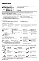
Installation Procedure Overview
The following is an overview of the steps required to install and setup the camera. All steps are explained in this document unless otherwise noted.
Preparation
1.
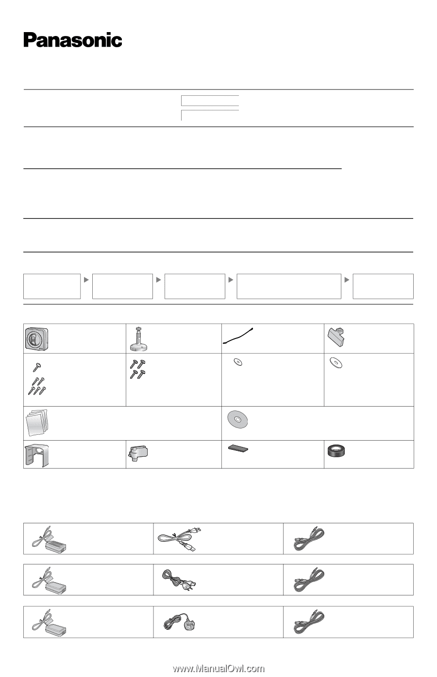
Confirm the following items are included in the camera’s packaging.
2.
You will need the following additional items to install and configure the camera.
Option
You can also connect the camera using the optional Panasonic BB-HCA7A, BB-HCA7CE or BB-HCA7E AC adaptor. The optional AC adaptor includes the
following items. (For more information, consult your authorized Panasonic dealer.)
• The AC adaptor, the AC adaptor cord, the AC cord, and the extension cord are not splash resistant, and are intended for indoor use only. The AC adaptor, the
AC adaptor cord, the AC cord, and the extension cord must be waterproofed for outside use.
Preparation
Confirm that you have all the
items required for
installation.
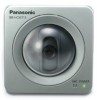
Camera Diagram
Make sure you know the
names of the camera’s
physical features.
Connections
Connecting the camera to
your network and to the power
outlet.
Setup
Setting up the camera (described in the included
Setup Guide). This involves configuring the camera
so that it can be accessed from a PC.
Mounting
Mounting or placing the
camera.
Main Unit (1 pc.)
Flexible Stand (1 pc.)
Order No. PNZMHCM515A
Safety Wire (1 pc.)
Order No. PQME10080Z
Used to secure the camera
when mounting it.
SD Card Cover (Hard
type) (1pc.)
[BB-HCM715 Only]
Order No. PNKV1065Z1
Screw A
BB-HCM715 (1pc.
for the
safety wire
)
Order No. PQHV2610PJ65
BB-HCM735 (1pc.
for the
safety wire,
4pcs.
for the
connector cover
)
Order No. XTN26+10GVW
Screw B (1pc.
for the safety
wire,
3pcs.
for the flexible
stand
)
Order No. XTB4+20AFJ
Washer S (1 pc.)
Order No. XWG26D12VW
Used when securing the
safety wire to the camera.
Washer L (1 pc.)
Order No. XWG4F16VW
Used when securing the
safety wire to the ceiling or
wall.
Important Information (1 pc.)
Installation Guide (this document) (1 pc.)
Setup Guide (1 pc.)
Stand-alone SD Memory Card Recording Guide (1 pc.)
Setup CD-ROM (1 pc.)
Order No. PNQC1016Z
Contains the Setup Program needed to configure the camera, as well as the
camera’s documentation.*
*See the included Important Information for a description of each document.
Sunshade (1pc.)
[BB-HCM735 Only]
Order No. PQKV10074Z1
Connector Cover (1pc.)
[BB-HCM735 Only]
Order No. PQYCHCM531A
Foam Strip (1pc.)
[BB-HCM735 Only]
Order No. PQHG10748Z
Self Bonding Tape (1pc.)
[BB-HCM735 Only]
Order No. PSHG1235Z
–
a PC (see the system requirements in the Important Information document)
–
a LAN cable (CAT-5 straight cable)
–
a router
BB-HCA7A
AC Adaptor (1 pc.)
Cord Length: About 3 m
(9 feet 10 inches)
AC Cord (1 pc.)
Cord Length: About 1.8 m
(5 feet 11 inches)
Extension Cord (1 pc.)
Cord Length: About 7 m
(23 feet)
BB-HCA7CE (2 pin AC cord)
AC Adaptor (1 pc.)
Cord Length: About 3 m
(9 feet 10 inches)
AC Cord (1 pc.)
Cord Length: About 1.8 m
(5 feet 11 inches)
Extension Cord (1 pc.)
Cord Length: About 7 m
(23 feet)
BB-HCA7E (3 pin AC cord)
AC Adaptor (1 pc.)
Cord Length: About 3 m
(9 feet 10 inches)
AC Cord (1 pc.)
Cord Length: About 1.8 m
(5 feet 11 inches)
Extension Cord (1 pc.)
Cord Length: About 7 m
(23 feet)
© Panasonic Communications Co., Ltd. 2009
PNQX2129ZA
KK0609CM0
Please read this document before using the product, and save this document for future
reference.
Panasonic Network Camera Website:
http://panasonic.net/pcc/ipcam/
• This document (Installation Guide) explains how to physically connect the
camera to the power supply and network, as well how to mount or place the
camera for regular use.
• The
Setup Guide
describes how to set up the camera so that it can be
accessed using a PC.
• Refer to the
Operating Instructions
on the
CD-ROM
for details regarding
the camera’s features.
• Refer to the
Troubleshooting Guide
on the
CD-ROM
if you have any
problems configuring or using the camera.
• The
Stand-alone SD Memory Card Recording Guide
describes how to
record images to an SD memory card without using a PC.
• The illustrations used in Installation Guide are of BB-HCM735.
Abbreviations
• UPnP is the abbreviation for “Universal Plug and Play”.
• The Network Camera is referred to as “the camera” in this document.
• The Setup CD-ROM is referred to as “the CD-ROM” in this document.
•
The term “SD memory card” is used in this document to refer to SD memory
cards and SDHC memory cards.