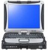
Panasonic CF-19KDRSXCM Service Manual
Panasonic CF-19KDRSXCM - Toughbook 19 Touchscreen PC Version Manual
 |
UPC - 092281888569
View all Panasonic CF-19KDRSXCM manuals
Add to My Manuals
Save this manual to your list of manuals |
Panasonic CF-19KDRSXCM manual content summary:
- Panasonic CF-19KDRSXCM | Service Manual - Page 1
ORDER NO. CPD0711208C1 Notebook Computer Model No. CF-19FHGAXxM This is the Service Manual for the following areas. M ...for U.S.A. and Canada Model No. CF-19FHGAX 1 M 1: Operation System A: Microsoft® Windows® XP Professional J: Microsoft® Windows® VISTA Business © 2007 Matsushita Electric - Panasonic CF-19KDRSXCM | Service Manual - Page 2
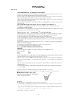
power point is earthed and that the installation is completely safe. For your safety, replacement fuse cover can be purchased from your local Panasonic Dealer. IF THE FITTED MOULDED PLUG IS UNSUITABLE plug is to be fitted please observe the wiring code as shown below. If in any doubt please consult - Panasonic CF-19KDRSXCM | Service Manual - Page 3
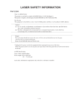
a stand alone drive. Danger: The serviceman should not remove the cover of drive unit and should not service because the drive unit is a nonserviceable part. Please check DANGER label on PD-drive unit. • Unplug the Laser safety information is appropriate only when drive with laser is installed. - Panasonic CF-19KDRSXCM | Service Manual - Page 4
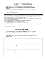
the leak. 4. Use only the power cord and batteries indicated in this manual. Do not dispose of batteries in a fire. They may explode. Check with local codes for possible special disposal instructions. SAVE THESE INSTRUCTIONS LITHIUM BATTERY This computer contains a lithium battery to enable the date - Panasonic CF-19KDRSXCM | Service Manual - Page 5
(Battery Pack) Troubleshooting Useful Information Getting Started Do Not Use with Any Other Product The battery pack is rechargeable Pack Other Than the One Specified Use only the specified battery pack with your product. Use of battery packs other than those manufactured and supplied by Panasonic - Panasonic CF-19KDRSXCM | Service Manual - Page 6
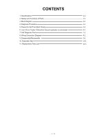
1. Specifications 2. Names and Functions of Parts 3. Block Diagram 4. Diagnosis Procedure 5. Power-On Self Test (Boot Check) 6. List of Error Codes 7. Self Diagnosis Test 8. Wiring Connection Diagram 9. Disassembly/Reassembly 10. Exploded View 11 - Panasonic CF-19KDRSXCM | Service Manual - Page 7
the Setup Utility ( Reference Manual "Setup Utility") and select [Information] menu. [CPU Speed]: CPU speed, [System Memory]: Memory size, [Hard Disk]: Hard disk drive size Main Specifications Model No. CPU Chipset Memory*2*4 Video Memory*1*3 Hard Disk Drive*4 CF-19FHGAXBM CF-19FDGAXVM Intel - Panasonic CF-19KDRSXCM | Service Manual - Page 8
Disable Utility*21 Setup Utility, Hard Disk Data Erase Installation Manual of "Trusted Platform Module (TPM)". *10 Only for model with ExpressCard slot *11 When using ExpressCard/34, the card slot cover cannot be closed. *12 Only for model with Smart Card slot *13 SD Memory Cards that support - Panasonic CF-19KDRSXCM | Service Manual - Page 9
Display Release Latch I: Speaker Reference Manual "Key Combinations" J: Function Key Reference Manual "Key Combinations" K: Keyboard L: Hard Disk Drive Reference Manual "Hard Disk Drive" M: Battery Pack N: Power Switch O: LED Indicator : Battery status Reference Manual "Battery Power" : Power status - Panasonic CF-19KDRSXCM | Service Manual - Page 10
1394 Interface Connector Reference Manual "IEEE 1394 Devices" D: Modem Port Reference Manual "Modem" E: LAN Port Reference Manual "LAN" F: SD Memory Card Indicator (Blinking: During access) Reference Manual "SD Memory Card" G: SD Memory Card Slot Reference Manual "SD Memory Card" H: Wireless Switch - Panasonic CF-19KDRSXCM | Service Manual - Page 11
LCD 10.4" XGA CRT CRT SW Internal Graphics Host PCI Bridge DRAM Interface 965-GM (1.05 ) INTEL HUB Interface 1.5V BIOS SPI 8M SATA (1.5Gb/s) USB AC-link Interface DMI Interface IDE Interface USB 2.0 Interface 1.5V INTEL LPC Bridge USB PCI Bridge PCI-E Bridge USB Digitizer Touch Screen - Panasonic CF-19KDRSXCM | Service Manual - Page 12
4 Diagnosis Procedure 4.1. Basic Procedures - Panasonic CF-19KDRSXCM | Service Manual - Page 13
of the following two points with regard to troubleshooting: 1. Know-how of diagnosis upon occurrence of heavy troubles, e.g. Set cannot be turned ON , Set fails to start , No display on screen , etc. 2. Explanation of each trouble, mainly symptom of trouble in operation. Flow Chart SSTTAARRTT Pay - Panasonic CF-19KDRSXCM | Service Manual - Page 14
condition of the main body is diagnosed by checking beep sound or error code. Start Test begins automatically when power switch is set to ON. Normal finish .....After memory checking, a beep sound is issued once and the set is placed (Note) A beep sound is also issued in case of other I/O trouble. - Panasonic CF-19KDRSXCM | Service Manual - Page 15
asterisk (*), write down the message and contact Panasonic Technical Support. If your system fails after you make changes in the Setup menus, reset the computer, enter Setup and install Setup defaults or correct the error. 0200 Failure Fixed Disk Fixed disk in not working or not configured properly - Panasonic CF-19KDRSXCM | Service Manual - Page 16
. If it cannot locate the address, it displays ????. Press to resume, to Setup Displayed after any recoverable error message. Press to start the boot process or to enter a Setup and change the settings. Write down and follow the information shown on the screen. Troubleshooting - Panasonic CF-19KDRSXCM | Service Manual - Page 17
HDD test This key is for service purpose only. Do not disclose this information to unrelated others. 1. Beginning of self-diagnosis test ɹ1-1. Setting of content of setup ɹɹɹɹ1.ɹThe power supply of the computer is turned on. ɹɹɹɹ2.ɹ" F2 " is pushed on the screen of "Panasonic" while " press - Panasonic CF-19KDRSXCM | Service Manual - Page 18
screen is displayed. -The item does not appear when the device of wireless LAN etc. is not physically connected. -The movement of the item must use an arrow key or a flat ends, the test result is displayed under the right of the screen. -Please click while diagnosing when being stop on the way by - Panasonic CF-19KDRSXCM | Service Manual - Page 19
pushed on the screen while "Pressto enter Setup" is displayed of "Panasonic". 3. Push "F10", and on the screen of "Is HDD enhancing test (60GB about 40 minutes Ex.The standard when the standard when the memory is increased according to the performance of the memory occasionally. - Panasonic CF-19KDRSXCM | Service Manual - Page 20
3. Test Item and Division of trouble Test item Stanard Enhancing Content of standard test CPU / SYSTEM CPU is shifted to protected mode, and "Violation of the paging", "Operation of the violation of a privileged instruction", and DMA, INT, TIMER, and the RTC operation are confirmed. Content - Panasonic CF-19KDRSXCM | Service Manual - Page 21
which uses main memory as VRAM may fail with main memory failure. It problems. The place with possibility of breakdown Main board/ Touch Screen tests. *3 The operator actually inputs the key, and the operator judges PASS/FAIL of the the test result is PASS, trouble is thought by not hearing of - Panasonic CF-19KDRSXCM | Service Manual - Page 22
CN2 INVERTER PCB CN1 CN2 BACK LIGHT HSDPA PCB TS PS2 PCB CN901 CN900 LCD Touch Screen Panel JK601 JK600 CN604 CN600 SERIAL EXTERNAL PORT DISPLAY PORT CN881 CN882 CN880 RTC CN804 TOUCH PAD CN800 RIGHT LED PCB CN780 SW PCB CN950 BAT FPC MAIN BATTERY CN807 CN805 GPRS CN802 LEFT - Panasonic CF-19KDRSXCM | Service Manual - Page 23
may result. 9.1. Disassembly Instructions 9.1.1. Preparation Before disassembling, the AC adaptor. ï Remove the optional DIMM memory card and PCMCIA card if they are connected. be recycled. Use new parts. 9.1.2. Removing the Battery Pack and HDD Pack HDD Case A 5. Remove the - Panasonic CF-19KDRSXCM | Service Manual - Page 24
1 2 10. Disconnect the Cable from Connector (CN800). 11. Remove the Touch Pad and Click Button Plate. Screws : DFHE5025XA Screws : DRSB2+5FKL 9.1.4. Removing the DIMM Lid Assíy DIMM Lid Ass'y Keyboard 4. Lift the far side of the Keyboard and slide - Panasonic CF-19KDRSXCM | Service Manual - Page 25
9.1.6. Removing the DU Lid Unit DIMM Lid Angle DU Lid Bluetooth PCB Antenna Cable(blue) HSDPA PCB Connector(CN1) Plate Clamper Connector(CN604) 1. Remove the 7 Screws . 2. Remove the DU Lid Angle and DU Lid. Screws : - Panasonic CF-19KDRSXCM | Service Manual - Page 26
the computer is not equipped with Wireless Module or Modem PCB. 1. Disconnect the 2 LCD Cables. (CN8,CN17) DU PCB < PCB. Connector(CN15) 5. Remove the 2 Screws , and remove the HDD Connector Guide. 6. Remove the 2 Screws. 7. Disconnect the Cable from the Connector. - Panasonic CF-19KDRSXCM | Service Manual - Page 27
the Connector (CN9). 3. Remove the Power SW PCB. Screw : DFHE5025XA 9.1.12. Removing the left LED and right LED PCB Release Paper Release Paper left LED PCB Connector(CN806) right LED PCB Connector(CN801) 1. Remove the two Release Papers. 2. Disconnect the Cable from the Connector (CN806 - Panasonic CF-19KDRSXCM | Service Manual - Page 28
2 Cables from the 2 Connectors (CN805,CN807). 2. Remove the 4 Screws . 3. Remove the Pad PCB. 1. Remove the 4 Screws . 2. Remove the LCD Hinge Cover. Hinge Cover SW PCB Operation Sheet 4. Remove the Operation Sheet and the SW PCB. Screws : DFHE5025XA 3. Display - Panasonic CF-19KDRSXCM | Service Manual - Page 29
(CN1,CN2). 2. Remove the Inverter Case and Inverter PCB. 3. Disconnect the 2 Cable from 2 connector (CN900,CN901). 4. Remove the TS PS2 PCB, then remove the LCD unit. 9.1.18. Removing WWAN Main Antenna PCB, LAN-Main BT Antenna PCB, LAN AUX Antenna PCB and WWAN AUX Antenna PCB WWAN Aux Pen - Panasonic CF-19KDRSXCM | Service Manual - Page 30
9.1.19. Removing the Each Cover DC IN LID Rubber USB LID Rubber LAN LID Rubber Moden/LAN LID Rubber Battery LID ASS'Y HDD LID ASS'Y Audio LID Rubber USB Back Rubber RGB LID Rubber Serial LID Rubber PCMCIA - Panasonic CF-19KDRSXCM | Service Manual - Page 31
Instructions 9.2.1. Attention when CF-19 series is repaired ï Please execute writing BIOS ID when you exchange the Main Board. ï Parts (Sheet and rubber) etc. related various the Conductive Cloth and Heat Spreader cannot be recycled. Use new parts. 9.2.2. Setting up the Inverter Ass'y and LCD - Panasonic CF-19KDRSXCM | Service Manual - Page 32
of the Frame within 0 to 0.5 mm at the far side. Screw the Board together 0 0.5mm LCD Back Dumper Remove the Release Paper on the back side and attach it. Lengthwise : Match to the LCD Frame. Crosswise : Match to the middle line. Digitizer PCB Ass'y Ensure the connector is connected securely - Panasonic CF-19KDRSXCM | Service Manual - Page 33
■ Assembly of Inverter PCB (Applicable Model : Touch Screen Model) Inverter Ass'y Confirm the direction of the Inverter board when attaching. 30 35mm Inverter Mil Sheet Insert it between the ribs. (Fit to the Cabinet.) LCD Side Cushion E Insulation Parts Insulation Parts Avoid any stress on - Panasonic CF-19KDRSXCM | Service Manual - Page 34
■ Assembly of Inverter PCB (Application Model : Digitizer Model) Details of cable 0 0 Inverter Ass'y LCD Back Dumper S5 Conductive Tape Attach coming over the end of steel plate by 1 to 2 mm. 0 1mm Avoid running over the rib Safety Working S2 - Panasonic CF-19KDRSXCM | Service Manual - Page 35
the jig) Dimensional tolerance: 0.2 T/S A Details of "A" Back Side 6 0.5mm TS FPC Spacer 0 0.5mm Touch Screen TS Spacer A Match to the wall of the Cabinet. 0 to 0.5 mm Attach the surface to the LCD Front. Avoid running over. 0 1mm 0 1mm TS Spacer B TS Spacer B Ensure 4 and 5 do not run - Panasonic CF-19KDRSXCM | Service Manual - Page 36
■ Assembly of Glass (Applicable Model : Digitizer Model) 9.2.3. Assembling the WWAN Main Antenna PCB, LAN-Main BT Antenna PCB, LAN AUX Antenna PCB, WWAN AUX Antenna PCB and Pen holder 1. Fix the Pen Holder using the 2 Screws. 2. Attach the Pen. 3. Fix the WWAN AUX Antenna PCB using the - Panasonic CF-19KDRSXCM | Service Manual - Page 37
Tape Pen Holder Cable Cushion Put the center of Cushion between the ribs. Cable Cushion Put the Cable on each hook 9.2.4. Setting up the LCD Hinge 1. Wind the Cable coming out of the LCD Unit counterclockwise to the LCD Hinge. 2. Set the Lock Plate and the Hinge Top Cover, and rotate the - Panasonic CF-19KDRSXCM | Service Manual - Page 38
Hold Plate Using the fixing jig when fixing the Hinge Fix Fix Screw LCD Hinge Safety Working Tighten S2 Avoid catching the Cable. If you arrange not need to use the fixing jig. Screw Avoid catching the Cable (when repairing or when not using the jig). Temporarily fix the both sides ("A") of - Panasonic CF-19KDRSXCM | Service Manual - Page 39
:Others S3:Sharp Edge Step1 Cable Holder Step2 Install the Holder and Cable guide on the Hinge as shown in figure. Cable Guide HInge Cable Holder Insert the cables into the Cable Holder as shown in figure. :Position of the Antenna Cables Right side of LCD Cable:White/Gray Left side of - Panasonic CF-19KDRSXCM | Service Manual - Page 40
: DXYN3+J10FNL Antenna Cover ■ Assembly of LCD Front Case Do not use if the protrusion such as painting lump exists around D5. (Due to affect the Touch Screen operations.) Tablet Latch Cover - Panasonic CF-19KDRSXCM | Service Manual - Page 41
Rear Case (Applicable Model : Touch Screen Model) (Note) Arrow without specified measurement: 0 to 0.5 mm Allowable right/left displacement of the Cushion: max. 0.5 mm Attach and apply the load 30 to 40N (3.0 to 4.0 Kgf). LCD Rear Cushion A LCD Rear Cushion A 0 0.5mm Marking line 0.5mm Marking - Panasonic CF-19KDRSXCM | Service Manual - Page 42
■ Assembly of Tablet Latch Cover and Antenna Cover Press and hold it against the cabinet, Tablet Lacth Cover and fix it using the Screw. Antenna Cover Press and hold it against the cabinet, and fix it using the Screw. Screw Locations Screw 10 Places Screw 16 Places Fix in the order. the front - Panasonic CF-19KDRSXCM | Service Manual - Page 43
using the 4 Screws . 3. Turn the computer over and fix the LCD Hinge Cover using the 2 Screws . Hinge Cover 4. Open the Display Unit and fix the LCD Hinge Cover using the 2 Screws . Screws : DFHE5025XA Screws : DRSB2+5FKL Screws - Panasonic CF-19KDRSXCM | Service Manual - Page 44
Note Avoid any stress on the Cable. Pass the Cable through the groove. Note: Running over affects the waterproof performance.. Black/White Blue/Gray Brown LCD UNIT Set to the Top Case Assy A LCD Cable Insert Position Order of fixing Screw Screw Screw Screw Screw Screw Screw Screw Close the - Panasonic CF-19KDRSXCM | Service Manual - Page 45
9.2.7. Setting the Pad PCB and SW PCB 1. Attach both the SW PCB and the Operation Sheet to the Cabinet. SW PCB 2. Connect the 3 Cables to the 3 Connectors. (CN800,CN805,CN807) 3. Fix the Pad PCB using the 4 Screws. Note: Tighten the Screws in the numbered order (No1 to No4). Screws : - Panasonic CF-19KDRSXCM | Service Manual - Page 46
Arrow without specified measurement: 0 to 0.5 mm PAD PWB ASSY PAD PWB SW FPC Insert PAD MAIN FPC ASSY No direction when inserting Back side LED(R) FPC Insert Power SW Cable Power Cable Cushion Insert Use the fixing JIG for the pressured portion when the cables are inserted. Wrap around the - Panasonic CF-19KDRSXCM | Service Manual - Page 47
the Cable to the Connector. (CN9) 2. Fix the Power SW PCB using the Screw. Screws : DFHE5025XA LED(R) PCB Ass'y Match the edge and attach it. LED Light Guide Sheet(R) LED PCB(R) LED PWB Tape(R) Match the edge and attach it. Connector(CN9) Power SW PCB ■ Assembly of the Power SW PCB - Panasonic CF-19KDRSXCM | Service Manual - Page 48
9.2.10. Setting the I/O PCB Ass'y 1. Fix the I/O PCB using the 2 Screws. 2. Fix the I/O PCB using the 4 Screws. Screws : DFHE5058ZB Screws : DRSB2+5FKL I/O PCB Ass'y 9.2.11. Setting the Main PCB, Wireless Module, SD PCB, DU PCB, Antenna PCB and - Panasonic CF-19KDRSXCM | Service Manual - Page 49
90 degrees. 11. Fix the BAT FPC Ass'y using the 2 Screws . 12. Connect the cable to the Connector. (CN15) 13. Fix the HDD Connector Guide using the 2 Screws . HDD Connector Guide Connector (CN882) SD PCB Ass'y BAT FPC Ass'y Connector(CN15) - Panasonic CF-19KDRSXCM | Service Manual - Page 50
DU PCB Antenna PCB Plate 17. Turn the computer over, open the Display Unit, and then connect the 2 LCD Cables. (CN8,CN17) Note: Tighten the Screws in the numbered order (No1 to No7). Screws : DFHE5108ZA Screws : DRSB2+10FKL Screws : DRSB2+5FKL - Panasonic CF-19KDRSXCM | Service Manual - Page 51
■ Assembly of Main PCB Process in the order of 1 2 3 4. Electric wire of the cabel is not sticked out from the black tape. Tape portion can be sticked out. Do not cover the screw Fold the tape Turn over Setting the MODEM label to the line S2 Do not cover the MODEM cable and Tape to the screw - Panasonic CF-19KDRSXCM | Service Manual - Page 52
- Panasonic CF-19KDRSXCM | Service Manual - Page 53
■ Assembly of Main Unit Screw Insert and then lock. Audio FPC Ass'y Stiffening Plate Side Audio FPC Lengthwise Attach it on the center of the FPC. 3mm Audio FPC Ass'y Insert it before setting the Main Board. DU PCB ASSY Tape Fold back Screw Screw Screw 0 1mm Apply the lubricant (sub - Panasonic CF-19KDRSXCM | Service Manual - Page 54
Thermal Rubber Screw HDD Connector Guide Screw A Screw SD PCB Ass'y Screw Screw Ensure that the knob is fit to SW when setting. DIMM HOLDER Ass'y RF SW Knob Insert the - Panasonic CF-19KDRSXCM | Service Manual - Page 55
Ensure that both top and bottom are hooked. Screw Screw Battery FPC Ass'y Insert the end of the Sheet into the space between the Main Board and the bottom of the PCMCIA Slot. (Left and Right 0.5mm, Apply 20 to 30N (2.0 to 3.0 Kgf)) Attach it fitting to the right 0 0.5mm 0 0.5mm Slide surface - Panasonic CF-19KDRSXCM | Service Manual - Page 56
9.2.13. Setting the HSDPA PCB and Bluetooth PCB 1. Fix the Plate and Bluetooth PCB using the 2 Screws . 2. Connect the Cable to the Connector. (CN1) 3. Connect the Cable to the Connector. (CN604) 4. Fix the Plate and the Board using the 4 Screws . 5. Attach the blue Antenna Cable to - Panasonic CF-19KDRSXCM | Service Manual - Page 57
■ Line Processing of Antenna Cable of Main Unit Cable Process 1/3 Place brown/blue/gray cables at left and white/black cables downward. After connecting the white antenna cable, connect it into the Holder as illustrated. After connecting the black antenna cable, connect it into the Holder as - Panasonic CF-19KDRSXCM | Service Manual - Page 58
Step 12 Connect the brown antenna cable. Step 13 Step 14 Cable Holder Cushion Insert it into the boss. (Push it downward from the top of boss.) Cable Connect the additional cable (black). Cable Process 3/3 Connect the grey antenna cable Connect the brown antenna cable Cable Holder Cushion Insert - Panasonic CF-19KDRSXCM | Service Manual - Page 59
9.2.14. Assembling the DU Lid Unit 1. Fix the DU Lid Angle and the DU Lid using the 7 Screws. Screws : DXQT2+D25FNL DIMM Lid Angle DU Lid 9.2.15. Setting the Rear Cabinet 1. Fix the Rear Cabinet on the Computer using the 13 Screws. - Panasonic CF-19KDRSXCM | Service Manual - Page 60
■ Cautions for Setting the Rear Cabinet (Note) Arrow without specified measurement: 0 to 0.5 mm Bottom Case Ass'y Bottom Rubber Bottom Rubber Match to the circles. 0 to 1mm Match to the wall. 0 to 1mm Match to the wall. 0 to 1mm 0 1mm Tape Potre Blind Sheet Rated Label Important Parts for - Panasonic CF-19KDRSXCM | Service Manual - Page 61
9.2.17. Setting the Touch Pad and Keyboard 1. Connect the Cable to the Connector (CN800), and attach the Touch Pad to the computer. 2. Set the Click Button Plate. 3. Attach the new TP Tape over the Touch Pad. 4. Attach the Palm Rest Ass'y on the computer. Keyboard Keyboard FPC TP Tape 7. Set the - Panasonic CF-19KDRSXCM | Service Manual - Page 62
Sheet Ensure it does not come over the end of the rib. 0 0.5mm Gasket E Ensure it does not come LCD Cushion Sheet over the end of the rib. The paste should be put the left side. Fit to the wall of the end side, and - Panasonic CF-19KDRSXCM | Service Manual - Page 63
■ Putting of the Palm Rest ASSY 3 5mm 6 8mm Windows Logo Label Intel Label 5 7mm 6 8mm Energy Star Label 4 6mm Remove the Release Paper, and then attach the Palmrest Assy. Remove the two-sided tape on the back side and attach it. After attaching, press by the load 30 to 40N (3.0 to 4.0 Kgf). - Panasonic CF-19KDRSXCM | Service Manual - Page 64
9.2.18. Setting the Battery Pack and the HDD Pack 1. Set the HDD in the HDD Case and fix it using the 2 Screws. HDD Case B HDD FPC Hooks HDD Hooks Heater 2. Open the HDD Cover and set the HDD Pack. 3. Open the Battery Cover and set the Battery. Screws : DXQT2+D4FNL - Panasonic CF-19KDRSXCM | Service Manual - Page 65
■ Assembly of the HDD ASSY Safety Working Heater Ass'y Heater 0 2mm Sub material: Pet Tape 1 (19mm width x 4 cm) Heater Insulation Sheet Attach on the inside of 1 Details for attachment of Heater Insulation Sheet 0 0.5mm Note for the Heater top end location 0 1mm Insulation Parts 10 15mm - Panasonic CF-19KDRSXCM | Service Manual - Page 66
9.2.19. Assembling the Each Cover 1. Fix the Battery LID Ass'y, the HDD LID Ass'y, and the PCMCIA LID Ass'y using the 6 Screws. 2. Set the Rear Cabinet. 3. Fix the Modem/LAN LID Rubber, the LAN LID Rubber, the USB LID Rubber, the DC IN LID Rubber, the Serial LID Rubber, the RGB LID Rubber, - Panasonic CF-19KDRSXCM | Service Manual - Page 67
-5 K80-7 Screw tightening torque A 0.2 +_ 0.02N m (2.0 +_ 0.2kgf cm) F 0.8 +_ 0.02N m E23 (8.0 +_ 0.2kgf cm) F N11 K5 K80-8 K80-11 K80-10 K80-8 F N11 K80 K80-1 K80-4 K80-3 K80-2 CF-19FHGAXxM - Panasonic CF-19KDRSXCM | Service Manual - Page 68
-8 K12-13-2 A K12-13-9 K12-13-7 K12-13-1 K12-13-6 K12-13-3 B K12-13-10 K12-13-1 B K12-16 B K12-16 K12-3-5 B K12-3-10 K12-3-4 CF-19FHGAXxM - Panasonic CF-19KDRSXCM | Service Manual - Page 69
A A N9 K126 K92 A N1 A N1 K165 A N1 E4 A N1 E406 K43 A N1 E409 E31 K42 A N1 Screw tightening torque A 0.2 +_ 0.02N m (2.0 +_ 0.2kgf cm) H 0.4 +_ 0.02N m (4.0 +_ 0.2kgf cm) CF-19FHGAXxM - Panasonic CF-19KDRSXCM | Service Manual - Page 70
K55 K14-1-2 K16 A N10 K16 A N10 N10 A N10 A K16 A N10 A N10 K1 K14-1-1 A K14-8 A K14-8 K85 K84 N6 N6 Screw tightening torque A 0.2 +_ 0.02N m (2.0 +_ 0.2kgf cm) CF-19FHGAXxM - Panasonic CF-19KDRSXCM | Service Manual - Page 71
D N17 K58 K67 K59 K57 K59 K59 K59 K54 K166 A N1 E15 K10-1 Screw tightening torque A 0.2 +_ 0.02N m (2.0 +_ 0.2kgf cm) D 0.8 +_ 0.08N m (8.0 +_ 0.8kgf cm) K10-1-4 E18 A N1 CF-19FHGAXxM - Panasonic CF-19KDRSXCM | Service Manual - Page 72
E36-15 E36-3 E36-14 E36-13 K66 E36-8 E36-11 E36-12 E36-11 E36-10 K71 Screw tightening torque A 0.18 +_ 0.02N m (1.8 +_ 0.2kgf cm) CF-19FHGAXxM - Panasonic CF-19KDRSXCM | Service Manual - Page 73
-6 Screw tightening torque B 0.2 +_ 0.02N m (2.0 _+ 0.2kgf cm) C 0.3 +_ 0.03N m (3.0 +_ 0.3kgf cm) D 0.8 +_ 0.08N m (8.0 _+ 0.8kgf cm) K11-1-6 K11-1-2 C N7 C N7 K11-9 B N15 D N16 B N15 D N16 B N15 C N7 K68 C N7 CF-19FHGAXxM - Panasonic CF-19KDRSXCM | Service Manual - Page 74
PCB, PR PCB, LED-RIGHT PCB, SD PCB, HSDPA PCB, POWERSW PCB, EXT ANT UNIT PCB, BT BAT FPC UNIT WWAN MAIN ANT WWAN AUX ANT LAN-MAIN BT ANT LAN AUX ANT CF-19 TS PCB UNIT WWAN COAXIAL CABLE LCD CABLE TS INVERTER HARD DISK KEYBOARD VISTA, U.S. MODEM CABLE MODEM DDR2-667 - Panasonic CF-19KDRSXCM | Service Manual - Page 75
SD LAN 24PIN) FPC, HSDPA 50PIN FPC, BT(19MK2 BT FPC 10PIN) FPC, PAD 40PIN FPC, LED LEFT 10PIN FPC, LED RIGHT 6PIN LITHIUM ION BATTERY PACK AC ADAPTOR AC CORD OPERATING INSTRUCTIONS(CF-19MK2) MANUAL(CF-19MK2 VISTA) MODEM CABLE TOUCHPANEL CLOTH RECOVERY DVD, VISTA SHOULDER BELT ASS'Y HOLDER HOLDER - Panasonic CF-19KDRSXCM | Service Manual - Page 76
DRQT26+D3KLT DXQT3+F4FNLT S DFKE9092YA-0 DFHG1669ZA DFHM0291ZA DFHM0294WA DFHM0295ZA S DFKE0892ZA-0 S DFKE0893YA-0 DFNW1604ZA LCD REAR CUSHION C LCD REAR CUSHION D LCD REAR CUSHION E TOUGHBOOK BADGE NEW PANASONIC BADGE TOP CASE ASS'Y TOP ELEPASS AUDIO WATERPROOF SHEET DSUB WATERPROOF SHEET PSW - Panasonic CF-19KDRSXCM | Service Manual - Page 77
HOLDER RF SW KNOB BAT CON HOLDER FS DUMMY CASE ANT CABLE HOLDER MP GUIDE SHEET PEN DU SPRING INSULATION PARTS DIMM THERMAL RUBBER EMI SHEET 10X20 CABLE HOLD PLATE ANT CABLE CUSHION LCD SIDE CUSHION E LCD SIDE CUSHION F DG TAPE INSULATION SHEET 30X140 TAPE PEN HOLDER CABLE HOLDER ANT COVER TABLET - Panasonic CF-19KDRSXCM | Service Manual - Page 78
HEAD SHEET BIS HEAD SHEET 2 WLAN SHEET RF-BT PLATE LCD CABLE TAPE CLAMP GASKET-65TSV10-4-15 GASKET-65TSV4-3-50 GASKET-65TSV13-1.5-20 POWER SPRING SHEET AHDESIVE TAPE RF LED PWB TAPE LED PWB TAPE CLICK BUTTON SHEET OPERATION SHEET KB WP SHEET LCD CUSHION SHEET TP BOTTOM TAPE HDD CASE SPACER KB CNT - Panasonic CF-19KDRSXCM | Service Manual - Page 79
DRYN3+J6FKL DRQT3+E4FKL DXYN2+J6FNL DXYN3+J10FNL DXYN3+J8FNL DXYN4+J8FNL XSB2+3FNL IO DC TUBE DIMM CUSHION ADHESIVE TAPE BAT INSULATION SHEET LCD CABLE PROTECTER CABLE GUIDE HINGE MCH SHEET COIN BAT SHEET LAN CONN HOLDER GASKET-65TSV13-1(T9)-1.9 THERMAL RUBBER CPU ICH RUBBER WATERPROOF SHEET - Panasonic CF-19KDRSXCM | Service Manual - Page 80
components use only manufacturer's specified parts. CF-19FHGAXxM REF. NO and AREA MAIN PCB 57, 61, 62, 63, 64, 65, 66, 67, 68, 69, 70, 71, 72, 73, 74, 75, 76, 77, 152, 153, 154, 155, 159, 161, 163 371, 372, 378, 379, 380, 381, 437, 473, 511, 515, 723, 742, 743 C 42, 78, 79, 80, 81, 83, 247, 248 - Panasonic CF-19KDRSXCM | Service Manual - Page 81
C 97, 255, 256, 315, 321, F1H1A1050015 CAPACITOR, 10V, 1µF 21 336, 337, 340, 341, 342, 343, 386, 387, 389, 390, 525, 603, 726, 740, 751, 768 C 98, 99, 100, 101, 102, F1G0J474A001 CAPACITOR, 6.3V, 0.47µF 7 103, 104 C 105, 106, 107, 108, 109, F1J0J226A051 CAPACITOR, 6.3V, 22µF 9 110, - Panasonic CF-19KDRSXCM | Service Manual - Page 82
C 766 F1G1H152A496 CAPACITOR, 50V, 1500pF 1 CF 1, 2, 3 D4CC1103A038 THERMISTOR 3 CN 2 K1MYL0B00003 CONNECTOR 1 CN 4 K1NAF0D00003 CONNECTOR 1 CN 5 K1KY42B00001 CONNECTOR 1 CN 6 K1FY104BA024 CONNECTOR, USB 1 CN 8 K1KA20AA0261 CONNECTOR 1 CN 9, 21, 42 K1MY24BA0310 - Panasonic CF-19KDRSXCM | Service Manual - Page 83
IC 23, 24, 25, 71 C0EBE0000460 IC 4 IC 26 C0EBH0000457 IC 1 IC 27 C2CBJA000003 IC, MICON 1 IC 30 C3FBLY000048 FLASH MEMORY 1 IC 31 C1CB00002790 IC, SECURITY CHIP 1 IC 33, 51, 52 C0JBAA000345 IC, LOGIC 3 IC 41 C0JBAA000380 IC 1 IC 42 C1CB00002723 CARDBUS CONTOLLER 1 IC - Panasonic CF-19KDRSXCM | Service Manual - Page 84
774, 775 R 28 ERJ2RKF56R0X RESISTOR, 1/16W, 56Ω 1 R 29 ERJ2RKF68R0X RESISTOR, 1/16W, 68Ω 1 R 30 ERJ2GEJ240X RESISTOR, 1/16W, 24Ω 1 R 36, 72, 180, 225 ERJ2RKF24R9X RESISTOR, 1/16W, 24.9Ω 4 R 38 ERJ2RKF2210X RESISTOR, 1/16W, 221Ω 1 R 40, 154, 155, 156, 486, D1H81034A024 RESISTOR - Panasonic CF-19KDRSXCM | Service Manual - Page 85
R 178, 286, 704 ERJ2GEJ471X RESISTOR, 1/16W, 470Ω 3 R 181 D1HA1048A001 RESISTOR ARRAY 1 R 182 D1H81504A024 RESISTOR ARRAY 1 R 205, 206, 211 D1H84724A024 RESISTOR ARRAY 3 R 207 D1H81044A024 RESISTOR, 1/16W, 100KΩ 1 R 208, 209 ERJ2RKF4530X RESISTOR, 1/16W, 453Ω 2 R 221, 364 - Panasonic CF-19KDRSXCM | Service Manual - Page 86
R 653, 749, 760, 777, 779, D1BDR033A099 RESISTOR, 1/3W, 0.033Ω 6 833 R 664 ERJ2GEJ684X RESISTOR, 1/16W, 680KΩ 1 R 666 ERJ2GEJ225X RESISTOR, 1/16W, 2.2MΩ 1 R 678, 682 ERJ6GEYJ122V RESISTOR, 1/10W, 1.2KΩ 2 R 679, 680 ERJ6GEYJ222V RESISTOR, 1/10W, 2.2KΩ 2 R 690 ERJ2GEJ393X - Panasonic CF-19KDRSXCM | Service Manual - Page 87
CN 902 K1MY12BA0309 CONNECTOR 1 CN 904 K1KA02BA0014 CONNECTOR 1 D 902 B0JDBE000002 DIODE 1 F 902 S K5H202Z00005 FUSE, 2A, 32V 1 IC 900 C1CB00002733 AUDIO CODEC 1 IC 901 C0CBCBC00130 IC, REGURATOR 1 IC 902 C0JBAE000306 IC, 1 IC 903 C0JBAS000251 IC 1 IC 904 - Panasonic CF-19KDRSXCM | Service Manual - Page 88
2A, 32V 1 IC 800 C0EBE0000460 IC 1 IC 801 C1DB00001417 IC, FLAT PAD CONTROLLER 1 Q 800, 801 B1GKCFJN0004 TRANSISTOR 2 R 800 ERJ2GEJ273X DIODE 1 SW 950, 951, 952, 953, 954, EVQPLDA15 SWITCH 6 955 LED-LEFT PCB CN 841 K1MY10AA0158 CONNECTOR 1 LD 841, 842, 843, 844, 845 - Panasonic CF-19KDRSXCM | Service Manual - Page 89
C 619 EEFCX0J121R CAPACITOR 1 C 622 F1G1H221A495 CAPACITOR, 50V, 220pF 1 CN 600 K1MN50BA0153 CONNECTOR 1 CN 601 K1MY52BA0190 CONNECTOR 1 CN 602 K1NA08E00013 SIM CONNECTOR 1 CN 604 K1MY10BA0309 CONNECTOR 1 D 600 B0KB00000044 DIODE 1 D 603 B0JCRC000002 DIODE 1 IC 600 - Panasonic CF-19KDRSXCM | Service Manual - Page 90
C 913, 916 F1J0J106A016 CAPACITOR, 6.3V, 10µF 2 C 914 F1G0J224A001 CAPACITOR, 6.3V, 0.22µF 1 CN 900 K1MN04B00073 CONNECTOR 1 CN 901 K1KA06BA0014 CONNECTOR 1 IC 900 C0EBE0000460 IC 1 IC 902 C1CB00002515 IC, TOUCHPANEL CONTROLLER 1 Q 900, 901 XP0431400L TRANSISTOR 2 Q 902
-
 1
1 -
 2
2 -
 3
3 -
 4
4 -
 5
5 -
 6
6 -
 7
7 -
8
-
9
-
10
-
11
-
12
-
13
-
14
-
15
-
16
-
17
-
18
-
19
-
20
-
21
-
22
-
23
-
24
-
25
-
26
-
27
-
28
-
29
-
30
-
31
-
32
-
33
-
34
-
35
-
36
-
37
-
38
-
39
-
40
-
41
-
42
-
43
-
44
-
45
-
46
-
47
-
48
-
49
-
50
-
51
-
52
-
53
-
54
-
55
-
56
-
57
-
58
-
59
-
60
-
61
-
62
-
63
-
64
-
65
-
66
-
67
-
68
-
69
-
70
-
71
-
72
-
73
-
74
-
75
-
76
-
77
-
78
-
79
-
80
-
81
-
82
-
83
-
84
-
85
-
86
-
87
-
88
-
89
-
90
 |
 |
ORDER NO.
CPD0711208C1
Notebook Computer
© 2007 Matsushita Electric Industrial Co., Ltd. All rights reserved.
Unauthorized copying and distribution is a violation of law.
CF-19FHGAXxM
Model No.
This is the Service Manual for
the following areas.
M …for U.S.A. and Canada
Model No. CF-19FHGAX
1
M
1: Operation System
A: Microsoft® Windows® XP Professional
J: Microsoft® Windows® VISTA Business