Panasonic CF-74CCBEBBM Service Manual
Panasonic CF-74CCBEBBM - Toughbook 74 - Core Duo 1.83 GHz Manual
 |
UPC - 092281861647
View all Panasonic CF-74CCBEBBM manuals
Add to My Manuals
Save this manual to your list of manuals |
Panasonic CF-74CCBEBBM manual content summary:
- Panasonic CF-74CCBEBBM | Service Manual - Page 1
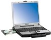
Model No. CF-74CCBAXBM ORDER NO. CPD0603050C1 Notebook Computer CF-74 This is the Service Manual for the following areas. M ...for U.S.A. and Canada © 2006 Matsushita Electric Industrial Co., Ltd. All rights reserved. Unauthorized copying and distribution is a violation of law. - Panasonic CF-74CCBEBBM | Service Manual - Page 2
1 - Panasonic CF-74CCBEBBM | Service Manual - Page 3
power cord to the equipment before opening the top cover of the drive. • When the power switch it on, do not place your eyes close to the front panel door to look into the interior of the unit. LASER Specification Class 1 level LASER Product Wave Length: DVD 658±8 nm CD 775~815 - Panasonic CF-74CCBEBBM | Service Manual - Page 4
3 - Panasonic CF-74CCBEBBM | Service Manual - Page 5
4 - Panasonic CF-74CCBEBBM | Service Manual - Page 6
CONTENTS 1. Specifications 1-1 2. Names and Functions of Parts 2-1 3. Block Diagram 3-1 4. Diagnosis Procedure 4-1 5. Power-On Self Test (Boot Check 5-1 6. List of Error Codes - Panasonic CF-74CCBEBBM | Service Manual - Page 7
) size: Run the Setup Utility and select [Information] menu. [CPU Speed]: CPU speed, [System Memory]: Memory size, [Hard Disk]: Hard disk drive size Main Specifications Model No. CF-74CCBAXBM / CF-74CCBADBM CPU Intel® Core™ Duo Processor T2400 (1.83 GHz, 2 MB*1 L2 cache, 667 MHz FSB) Chipset - Panasonic CF-74CCBEBBM | Service Manual - Page 8
Windows® XP Professional Service Pack 2 with Advanced Hard Disk Backup Utility*25, Hard resolution depends on the specifications of the external display. Manual of "Trusted Platform Module (TPM)". *14 This slot does not support the MultiMedia card. Operation has been confirmed for Panasonic SD Memory - Panasonic CF-74CCBEBBM | Service Manual - Page 9
LED indicator : Caps lock : Numeric key (NumLk) : Scroll lock (ScrLk) : Multimedia pocket device status or the second battery status : Hard disk drive status M :Keyboard N :Touch pad O :Microphone jack You can use a stereo condenser microphone. Connecting other type - Panasonic CF-74CCBEBBM | Service Manual - Page 10
cable. Refer to the instruction manual of the cable. P : Battery pack Q :Battery latch R :Multimedia pocket release button G :SD Memory Card indicator (Blinking: During access or a password is requested) H :Ventilation hole I : Stylus holder J : DC-IN jack S : Hard disk drive latch T : RAM module - Panasonic CF-74CCBEBBM | Service Manual - Page 11
Ethernet GBe Yukon Ultra Marvell MiniCard PCI Express Bus Express Card GBE antenna Wireless LAN Golan 11ABG PM Signals SO-DIMM Main Memory DDR2 SDRAM SO-DIMM Extension Memory DDR2 SDRAM 3.3V 32bit PCI Bus 33MHz PCMCIA R5C811A/812A SD Card Smart Card TYPE II RJ11 Data Modem Agere or - Panasonic CF-74CCBEBBM | Service Manual - Page 12
4 4.1. 4-1 - Panasonic CF-74CCBEBBM | Service Manual - Page 13
contact of K/B connector in use. Replace keyboard or main board. Trouble symptoms on some of DVD or CD NO YES Replace DVD drive. Replace main board. Check if there are any flaws on DVD or CD media. Since flaws may appear on specific media, DVD or CD media can be defective. Each kind - Panasonic CF-74CCBEBBM | Service Manual - Page 14
or error code. z Start Test begins automatically when power switch is set to ON. z Normal finish .....After memory checking, a beep sound is issued once and the set is placed into automatic stop. Note: If no error offering (Note) A beep sound is also issued in case of other I/O trouble. 5-1 - Panasonic CF-74CCBEBBM | Service Manual - Page 15
problems. If your system displays one of except the messages marked below with an asterisk (*), write down the message and contact Panasonic Technical Support was detected. 0232 Extended RAM Failed at offset : nnnn Extended memory not working or not configured properly at offset nnnn. 0250 System - Panasonic CF-74CCBEBBM | Service Manual - Page 16
- Cache disabled Contact Panasonic Technical Support. 02F0: CPU ID: CPU socket number for Multi-Processor error. 02F4: EISA CMOS not writable ServerBIOS2 test error: Cannot write to EISA CMOS. 02F5: DMA Test Failed ServerBIOS2 test error: Cannot write to extended DMA (Direct Memory Access) registers - Panasonic CF-74CCBEBBM | Service Manual - Page 17
7 Diagnostic Test Diagnostic Test Procedure 7.1. Equipment (1) Test Computer 1 unit (2) External Floppy Disk Drive (USB Port 1 unit (3) AC Adapter 1 pc. (4) Loopback Plug (Serial Port Test for RS232C) [P/N: DFWV95C0067] ----- 1 pc. (5) Floppy Disk containing file DIAG 1 pc. 7.2. Preparation (1) - Panasonic CF-74CCBEBBM | Service Manual - Page 18
disk you insert into the drive. Use a formatted disk that setup utility Turn on the power. When "Panasonic Press F2 to enter setup" appears on and press Enter. Menu Screen 1. DIAG on FD (CF-74) 2. HDD read Test 3. LAN test 4. SD I/F Problems in the unit are located and divided according to - Panasonic CF-74CCBEBBM | Service Manual - Page 19
memory on/off test Floating point processor function test Memory standard test DMA page register test DAM register test DAM transfer test Interrupt controller halt instruction models Select and press Enter for DIAG on FD 1. DIAG on FD (CF-74) 2. HDD read Test 3. LAN test 4. SD I/F test 5. Modem - Panasonic CF-74CCBEBBM | Service Manual - Page 20
For explanations of error messages, see Error Messages and Problem Categories (section 8.5). Quitting the test At the screen be sure to choose the following items and press Enter. 2. HDD read Test 1. DIAG on FD (CF-74) 2. HDD read Test 3. LAN test 4. SD I/F test 5. Modem I/F test 6. Wireless LAN - Panasonic CF-74CCBEBBM | Service Manual - Page 21
Test Selection Starting up the input menu 1. From the menu screen shown below, choose Quit and press Enter. 1. DIAG on FD (CF-74) 2. HDD read Test 3. LAN test 4. SD I/F test 5. Modem I/F test 6. Wireless LAN test (Wireless LAN AB G Model only) Q. Quit Select please [ 1, 2, 3, 4, 5, 6, Q ] ? menu - Panasonic CF-74CCBEBBM | Service Manual - Page 22
test condition settings for to be changed, press "A" for Additional custom test items. and "R" for Erase. Example: All initial V Alues are "0" so set CF-74 TEST1. . tests other than the necessary ones to "1". Press "C" twice to return the menu screen. To save the selected list, press "AL - Panasonic CF-74CCBEBBM | Service Manual - Page 23
8.5 . Error Messages and Troubleshooting The table below explains the parts that NPU OPERAND TEST 4 RAM (Memory related) RAM STANDARD 5 CONTROL DMA PAGE REG TEST 6 (Control ICs on the DMA REGISTER TEST 7 main board, etc.) DMAC Transfer TEST 8 PIC HALT INSTRUCTION TEST 9 PIC REGISTER TEST - Panasonic CF-74CCBEBBM | Service Manual - Page 24
JACK MODEM MODEM JACK USB CN16 ANTENNA PCB L CN28 MAIN PCB CN5 CN25 CN4 DIMM MEMORY CARD CN8 CN2 CN3 SPEAKER (L) CN1002 USB PCB CN1701 USB CN1702 DC-IN JK1501 CN1501 DC-IN PCB DVD-ROM DRIVE FAN MOTOR LITHIUM BATTERY WIRELESS MODULE ANTENNA PCB R JK2 JK1 Headphone Microphone KBD FPC - Panasonic CF-74CCBEBBM | Service Manual - Page 25
operation may result. 10.1. Disassembly Instructions 10.1.1. Preparation Before disassembling, be the AC adaptor. • Remove the optional DIMM memory card and PCMCIA card if they are connected. Battery Pack, the HDD Unit and the DVD-ROM Drive Unit 10.1.3. Removing the HDD Hook Hook Hook HDD - Panasonic CF-74CCBEBBM | Service Manual - Page 26
Card 1. Remove the two Screws , and remove the DIMM Cover. 2. Open the right and left Hooks of the DIMM Memory Card outward, and remove the DIMM Memory Card. Screws : XSB2+3FNL 10.1.5. Removing the Keyboard Keyboard Connector (CN25) KBD FPC 5. Remove the KBD WP Sheet. 6. Disconnect the - Panasonic CF-74CCBEBBM | Service Manual - Page 27
Rubbers and remove the Bottom Cover. Screws : DXSB2+6FNL Screws : DXYN2+J16FNL Screws : DXYN2+J8FNL CN7 CN24 CN26 CN28 CN19 MP Guide 10-3 - Panasonic CF-74CCBEBBM | Service Manual - Page 28
ten Connectors (CN6, CN7, CN24, CN19, CN28, CN21, CN802, CN18, CN15, CN25). 2. Remove the six Screws . 3. Remove the Main PCB. 4. Remove the MP Guide. Screws : DFHE5025XA 10.1.11. Removing the PC Card Ejector and Lithium Battery Lithium Battery (to CN14) PC Card Ejector 1. Remove the two - Panasonic CF-74CCBEBBM | Service Manual - Page 29
10.1.14. Removing the USB PCB CN1701 10.1.16. Removing the LCD Front Cabinet LCD Leg Rubber LCD Leg Rubber USB PCB 1. Disconnect the Cable from the Connector (CN1701). 2. Remove the two Screws . 3. Remove the USB PCB. Screws : DFHE5025XA 10.1.15. Removing the Display - Panasonic CF-74CCBEBBM | Service Manual - Page 30
1. Disconnect the LCD/INV. Cable from the Connector on the Inverter. 2. Remove the LCD Unit. 3. Remove the Inverter with the Inverter Case. 4. Remove the two Screws , and then the W-LAN PCB L and R. Screws : XQN17+BJ6FJ 10.1.18. Removing the Touch PAD and PAD PCB 1. Remove the Palm Rest - Panasonic CF-74CCBEBBM | Service Manual - Page 31
10.2. Reassembly Instructions 10.2.1. Attention when CF-74 series is repaired • Please execute writing BIOS ID when you exchange the Main Board. • You cannot reuse the Conductive Clothes and the heat dissipating parts - Panasonic CF-74CCBEBBM | Service Manual - Page 32
n Attaching the LCD Damper C and LCD Damper D 1. Attach the four LCD Damper C to the upper part and lower part of the LCD Unit. 2. Attach the LCD Damper D to the upper center of the LCD Unit. A A LCD Damper D 0~1mm Match the LCD Damper D to the center of the LCD Unit. LCD Unit LCD Display Side - Panasonic CF-74CCBEBBM | Service Manual - Page 33
n Arranging the TP Power Cable and Attaching the TP/LCD Sheet Ensure the Tape does not cover the Connecter port. Safety Working Match the end of the Sheet to the end of the Connecter. Sheet Connect the Connector. TP Power Cable Ensure the Tape and Cable Sheet do not come out of the metal part. - Panasonic CF-74CCBEBBM | Service Manual - Page 34
n Cautions for Setting the LCD Unit LCD Unit Ensure the Cushion does not run over the rib of the LCD Rear Cabinet. (Same on the upper side.) Safety Working Pull and hold the Cables, and set the LCD. (Avoid them from being caught inside the LCD unit.) LCD Rear Cabinet Ensure the Cushion does not - Panasonic CF-74CCBEBBM | Service Manual - Page 35
10.2.3. Setting the LCD Front Cabinet 1. Set the LCD Front Cabinet to the LCD Rear Cabinet. 2. Fix the LCD Front Cabinet using the two Screws. 3. Fix the LCD Front Cabinet using the two Screws, and attach the two LCD Leg Rubbers. Screws : DRHM0075ZA Screws : DXQT2+G4FCL n Fixing - Panasonic CF-74CCBEBBM | Service Manual - Page 36
the Cable into this side. Ensure the Cable does not come out of the board edge so that the Cable does not touch the MP Drive. Pass it through the notch. Avoid runnning over the boss. MP Slide Sheet Fit the Cable between the pins. Pass it through the rib. Ensure - Panasonic CF-74CCBEBBM | Service Manual - Page 37
10.2.6. Setting the SD PCB, Heat Sink and FAN Motor 1. Connect the SD FFC to the Connector (CN1401). 2. Fix the SD PCB to the computer using the three Screws. 3. Set the Heat Sink, Fan Duct and the four Heat Sink Springs. 4. Fix the FAN Motor to the computer using the two Screws. - Panasonic CF-74CCBEBBM | Service Manual - Page 38
10.2.7. Setting the DC-IN PCB and I/O PCB 1. Fit the Modem Cable and LAN Cable between the MODELAN Holders, and set them on to the computer. 2. Fix the I/O PCB to the I/O Plate using the four Screws. 3. Fix the I/O PCB with I/O Plate to the computer using the two Screws. 4. Fix the DC-IN - Panasonic CF-74CCBEBBM | Service Manual - Page 39
PCB 10.2.9. Setting the Main PCB Note: After replacing the Main Board, rewrite the BIOS ID. 1. Set the MP Guide to the Main PCB. 2. Set the Main PCB to the computer. 3. Fix the Main PCB using the six Screws< Main PCB CN6 CN21 CN802 CN18 CN15 CN7 CN24 CN26 CN28 CN19 MP Guide 10-15 - Panasonic CF-74CCBEBBM | Service Manual - Page 40
n Arranging the Cables to the Cable Holder and their Wiring Order • Pull the surplus length of the Cable coming from the LCD side to inside of the unit. (If the surplus length comes outside, it will be caught by the center cover during setting.) • Fit the Cables to the corresponding grooves of the - Panasonic CF-74CCBEBBM | Service Manual - Page 41
10.2.10. Setting the Wireless Module and MDC Module 1. Connect the Modem Cable to the Connector, and fix the MDC Module to the Main PCB using the two Screws. 2. Connect the Wireless Module to the Connector of the Main PCB, and fix it using the two Screws. 3. Connect the two Antenna - Panasonic CF-74CCBEBBM | Service Manual - Page 42
10.2.11. Setting the Bottom Case 1. Set the Bottom Case. 2. Fix the Bottom Case using the ten Screws. No1 to No10 3. Fix the Bottom Case using the six Screws. No11 to No16 4. Fix the Bottom Case using the two Screws. No17, No18 5. Close the Lid Covers. Note: Tighten the Screws in the - Panasonic CF-74CCBEBBM | Service Manual - Page 43
10.2.13. Setting the Speaker and the LED PCB 1. Fix the LED PCB using the two Screws. 2. Set the Speaker L and R to the computer. 3. Connect the Speaker Cable L and R to the two Connec- tors (CN1002, CN1003) on the LED PCB. 4. Fix the Speaker Cable L and R using the Tape. 5. Fix the Speaker L - Panasonic CF-74CCBEBBM | Service Manual - Page 44
10.2.14. Setting the Keyboard 1. Connect the KBD FPC Cable to the Connector (CN25) of the Main PCB. 2. Connect the two Cables of the Keyboard to the two Connectors on the KBD FPC. 3. Remove the Release Paper of the KBD WP Sheet, and attach the KBD WP Sheet to the computer as it covers the Cable of - Panasonic CF-74CCBEBBM | Service Manual - Page 45
the DIMM Cover using the two Screws. Screws : XSB2+3FNL Hook DIMM Cover DIMM Memory Card Hook 10.2.16. Setting the Battery Pack, the HDD Unit and the DVD-ROM Drive Unit 1. Set the DVD-ROM Driver Unit. 2. Set the HDD Pack. 3. Set the Battery Pack. 4. Slide the - Panasonic CF-74CCBEBBM | Service Manual - Page 46
E2 B N9 K39 K44 Screw tightening torque K9 A 0.1 ± 0.01 N.m D 1.2 ± 0.1 N.m (1.0 ± 0.1 kgf.cm) (12.0 ± 1.0 kgf.cm) CB 0.2 ± 0.02 N.m F 0.8 ± 0.1 N.m (2.0 ± 0.2 kgf.cm) (8.0 ± 1.0 kgf.cm) K39 K32 C 0.4 ± 0.02 N.m (4.0 ± 0.2 kgf.cm) CF-74CCBAXBM - Panasonic CF-74CCBEBBM | Service Manual - Page 47
.cm) K96 K84 K86 K2 K91 B N7 B N5 K91 B N1 B N3 K90 B N8 B N7 K88 K93 B N5 B N7 B N9 K12 K94 K20 K15 B N9 K57 CF-74CCBAXBM - Panasonic CF-74CCBEBBM | Service Manual - Page 48
G N15 K202 G N15 K207 K206 K22 E24 K207 Screw tightening torque A 0.1 ± 0.01 N.m (1.0 ± 0.1 kgf.cm) B 0.2 ± 0.02 N.m (2.0 ± 0.2 kgf.cm) F 0.8 ± 0.1 N.m (8.0 ± 1.0 kgf.cm) G 0.375 ± 0.025 N.m (3.75 ± 0.25 kgf.cm) CF-74CCBAXBM - Panasonic CF-74CCBEBBM | Service Manual - Page 49
E22-6-4 E22-6-5 E22-6-1-1 E22-6-5 E22-2 E22-4 a E22 E22-1 E22-5 E22-4 E22-6-3 E22-4 E22-3 E22-6-1 E22-6-4 E22-6-6 E22-6-2 E22-4 E22-6 CF-74CCBAXBM - Panasonic CF-74CCBEBBM | Service Manual - Page 50
. When replacing any of these components, use only manufacturer's specified parts. CF-74CCBAXBM REF.NO. and AREA Main Block Unit E1 E2 E3 E4 E5 E6 HDD CN HDD FPC, KBD DRAIVE, DVD-ROM & CD-R/RW BEZEL ASSY FPC, MP DRIVE LCD UNIT ASS'Y LCD UNIT LCD DAMPER A LCD DAMPER B LCD DAMPER C LCD DAMPER - Panasonic CF-74CCBEBBM | Service Manual - Page 51
1 Accessories A1 CF-AA1683AM1 AC ADAPTOR 1 A2 N4HUNTA00001 LITHIUM ION BATTERY PACK 1 A3 DFQX5582ZA MANUAL 1 A4 K2CG3DR00003 COVER 1 1 K16 DFHG1857ZA ANTENNA COVER CUSHION 1 K17 DFHG6034ZB MP GUIDE 1 K18 DFHM0386ZA-0 IO COVER PLATE 1 K19 DFHM0388ZA KBD ANGLE 1 - Panasonic CF-74CCBEBBM | Service Manual - Page 52
DFHR6221ZA LED LENZ POWER 1 K46 DFHR6234ZB CABLE HOLDER 1 K47 DFHR6235ZA FAN DUCT 1 K48 DFHR6242ZA JACK SPACER 1 K49 DFHR9122ZA HDD GUIDE ASSY 1 K50 DFHG1818ZA-0 SPEAKER RUBBER 2 K51 DFHM0387ZB IO PLATE 1 K52 DFHR3591ZB INSU SHEET CHIP SET 1 K53 DFGT0944YA MP SET - Panasonic CF-74CCBEBBM | Service Manual - Page 53
CASE 1 K202 DFKF0266ZA-0 LCD FRONT 1 K203 DFHR3599ZA TP/LCD SHEET 1 K204 DFHG1399XA-0 LCD LEG RUBBER 2 K205 DFHR3C84ZA-0 PANASONIC BADGE 1 K206 DFMX0778ZA SHEET 1 K207 DFHE0277ZA GASKET 5 K208 DFHE0418ZA LID MAGNET 1 K209 DFHE0465ZA EMI SHEET 5 1 K210 DFKM9035ZA - Panasonic CF-74CCBEBBM | Service Manual - Page 54
important for safety. When replacing any of these components use only manufacturer's specified parts. CF-74CCBAXBM REF. NO and AREA MAIN PCB C1 C2 C3 C4 C5 C7 C 50 C 51 C 54 C 55 C 58 C 59 C 60 C 71 C 72 C 73 C 74 C 76 C 77 C 78 C 79 C 80 C 81 C 83 C 84 C 87 C 90 C 95 C 96 C 97 - Panasonic CF-74CCBEBBM | Service Manual - Page 55
C 125 C 126 C 149 C 152 C 154 C 156 C 157 C 158 C 161 C 163 C 164 C 165 C 166 C 169 C 170 C 172 C 173 C 174 C 175 C 177 C 178 C 179 C 180 C 181 C 182 C 183 C 184 C 185 C 186 C 187 C 188 C 189 C 190 C 202 C 203 C 204 C 205 C 206 C 207 C 208 C 209 C 212 C 215 C 216 C 217 C 218 C 219 C 220 C 221 C 223 - Panasonic CF-74CCBEBBM | Service Manual - Page 56
C 224 C 225 C 226 C 228 C 229 C 230 C 231 C 234 C 235 C 236 C 237 C 241 C 246 C 247 C 248 C 250 C 251 C 253 C 263 C 266 C 281 C 282 C 286 C 287 C 288 C 291 C 296 C 297 C 298 C 300 C 301 C 304 C 306 C 308 C 309 C 310 C 311 C 314 C 327 C 347 C 349 C 351 C 352 C 353 C 356 C 357 C 358 C 365 C 372 C 373 - Panasonic CF-74CCBEBBM | Service Manual - Page 57
C 389 C 397 C 400 C 401 C 402 C 403 C 406 C 412 C 417 C 428 C 431 C 432 C 433 C 446 C 447 C 450 C 457 C 458 C 459 C 460 C 461 C 462 C 463 C 467 C 817 C 824 C 861 C 892 C 893 C 921 C 922 C6 EEFUD0D271ER CAPACITOR, 2V, 270µF 2 C 171 C 10 F1J0J4750019 CAPACITOR, 6. - Panasonic CF-74CCBEBBM | Service Manual - Page 58
C 12 C 13 C 14 C 15 C 16 C 17 C 18 C 20 C 21 C 22 C 23 C 24 C 25 C 26 C 27 C 28 C 29 C 30 C 31 C 32 C 33 C 34 C 35 C 37 C 38 C 39 C 40 C 41 C 42 C 43 C 44 C 45 F1J0J106A016 CAPACITOR, 6.3V, 10µF 44 C 56 C 57 C 64 C 75 C 82 C 85 C 86 C 93 C 94 C 102 C 109 - Panasonic CF-74CCBEBBM | Service Manual - Page 59
C 200 C 201 C 211 C 213 C 243 C 245 C 265 C 269 C 271 C 283 C 307 C 318 C 421 C 422 C 426 C 427 C 804 C 811 C 815 C 818 C 819 C 831 C 845 C 863 C 879 C 46 F1G1H222A496 CAPACITOR, 50V, 2200pF 1 C 61 F1H0J1050022 CAPACITOR, 6.3V, 1µF 24 C 63 C 65 C 66 C 69 C 91 C - Panasonic CF-74CCBEBBM | Service Manual - Page 60
C 62 EEFCX0D221R CAPACITOR, 2V, 220µF 3 C 88 C 89 C 155 EEFCX0E221R CAPACITOR, 1 C 108 F1G1A104A014 CAPACITOR, 10V, 0.1µF 18 C 143 C 144 C 145 C 146 C 147 C 148 C 238 C 239 C 319 C 320 C 321 C 322 C 323 C 336 C 348 C 438 C 439 C 110 D4CC1103A038 THERMISTOR 2 C 830 - Panasonic CF-74CCBEBBM | Service Manual - Page 61
C 452 C 808 C 823 C 864 C 888 C 889 C 891 C 920 C 924 C 150 F1H1A1050015 CAPACITOR, 10V, 1µF 24 C 151 C 153 C 159 C 168 C 197 C 214 C 222 C 227 C 242 C 256 C 267 C 268 C 272 C 276 C 277 C 317 C 325 C 326 C 390 C 842 C 865 C 923 C 926 C 193 F1G1H4R0A543 CAPACITOR - Panasonic CF-74CCBEBBM | Service Manual - Page 62
C 424 C 832 C 834 C 844 C 847 C 849 C 851 C 869 C 882 C 917 C 273 F1G1H221A496 CAPACITOR, 50V, 220pF 7 C 275 C 360 C 393 C 394 C 395 C 875 C 285 F1G1H330A542 CAPACITOR, 50V, 33pF 1 C 289 F1J1E105A080 CAPACITOR, 25V, 1µF 4 C 290 C 292 C 293 C 312 F1H1A105A030 - Panasonic CF-74CCBEBBM | Service Manual - Page 63
C 468 C 382 ERJ2RKF1500X RESISTOR, 1/16W, 150Ω 3 C 386 C 388 C 415 F1G1A683A014 CAPACITOR, 10V, 0.068µF 1 C 425 F1G1E472A062 CAPACITOR, 25V, 4700pF 1 C 436 F1G1H471A496 CAPACITOR, 50V, 470pF 2 C 437 C 442 ECJ2FF1A106Z CAPACITOR, 10V, 10µF 2 C 455 C 801 EEFSX0D331ER - Panasonic CF-74CCBEBBM | Service Manual - Page 64
, 25V, 1µF 2 C 910 C 927 DCUI1C106HDB CAPACITOR, 16V, 10µF 3 C 931 C 934 C 929 F1G1H152A496 CAPACITOR, 50V, 1500pF 1 CF 1 D4CC1103A038 THERMISTOR 1 CN 2 K1MML0B00003 CONNECTOR 1 CN 3 K1MYL0B00001 CONNECTOR 1 CN 4 K1KA02BA0014 CONNECTOR 1 CN 5 K1MY52B00001 CONNECTOR - Panasonic CF-74CCBEBBM | Service Manual - Page 65
D1 MA2J72900L DIODE 6 D2 D3 D9 D 23 D 42 D4 MA3J741E0L DIODE 1 D 10 B0JCPD000023 DIODE 9 D 801 D 804 D 827 D 828 D 829 D 830 D 835 D 836 D 12 B0ADDH000004 DIODE 13 D 13 D 14 D 15 D 16 D 17 D 18 D 21 D 22 D 24 D 837 D 838 D 839 D 19 B0KB00000044 DIODE 3 D - Panasonic CF-74CCBEBBM | Service Manual - Page 66
D 813 MAZ80620ML DIODE 6 D 815 D 816 D 817 D 818 D 819 D 820 B2ABAM000002 DIODE 1 D 825 MAZ81800ML DIODE 1 D 826 MAZ81200ML DIODE 1 D 831 B0JDBE000002 DIODE 3 D 833 D 834 D 832 B0JDRE000007 DIODE 1 F1 K5H202Z00005 FUSE, 2A 5 F2 F4 F5 F9 F3 K5H402Z00003 FUSE, - Panasonic CF-74CCBEBBM | Service Manual - Page 67
IC 74 IC 30 IC 58 IC 33 IC 35 IC 812 IC 36 IC 37 IC 39 IC 40 IC 44 IC 47 IC 51 IC - Panasonic CF-74CCBEBBM | Service Manual - Page 68
L 14 L 15 L 16 L 17 L 18 L 19 L 24 L 25 L 30 L 31 L 32 L 33 L 43 L 12 J0MAB0000200 INDUCTOR 6 L 20 L 21 L 34 L 44 L 45 L 37 DDB5Z021C-Y INDUCTOR 6 L 38 L 39 L 40 L 41 L 42 L 801 G1AR56PA0001 INDUCTOR 2 L 802 L 803 G1C2R8MA0022 INDUCTOR 1 L 804 G1C4R7MA0022 - Panasonic CF-74CCBEBBM | Service Manual - Page 69
Q 830 Q 832 Q 833 Q 834 Q 836 Q 837 Q 838 Q 852 Q 858 Q 859 Q 870 Q 871 Q 872 Q 873 Q 879 Q 880 Q 12 B1GBCFJN0037 TRANSISTOR 10 Q 844 Q 846 Q 851 Q 854 Q 855 Q 856 Q 857 Q 862 Q 868 Q 13 B1GFCFNN0019 TRANSISTOR 6 Q 69 Q 70 Q 72 Q 869 Q 874 Q 19 XP0421300L - Panasonic CF-74CCBEBBM | Service Manual - Page 70
Q 803 Q 809 Q 815 Q 816 Q 819 Q 825 Q 826 Q 865 Q 866 Q 867 Q 881 Q 27 B1DHDC000028 TRANSISTOR 2 Q 57 Q 28 XP0411500L TRANSISTOR 7 Q 29 Q 30 Q 31 Q 32 Q 33 Q 34 Q 79 B1GDCFNN0031 TRANSISTOR 8 Q 804 Q 829 Q 845 Q 847 Q 853 Q 860 Q 861 Q 801 B1CFRD000009 - Panasonic CF-74CCBEBBM | Service Manual - Page 71
Q 878 Q 882 Q 850 B1GFCFJN0016 TRANSISTOR 2 Q 885 Q 863 B1DDDC000003 TRANSISTOR 2 Q 864 Q 883 B1DHFD000015 TRANSISTOR 1 R2 ERJ2GEJ102X RESISTOR, 1/16W, 1KΩ 13 R 63 R 66 R 67 R 111 R 156 R 159 R 227 R 228 R 330 R 337 R 406 R 434 R3 ERJ2RKF1500X RESISTOR, 1/16W, 150Ω - Panasonic CF-74CCBEBBM | Service Manual - Page 72
R 870 R 872 R 877 R 19 ERJ2GEJ562X RESISTOR, 1/16W, 5.6KΩ 5 R 916 R 925 R 927 R 968 R 20 ERJ2GEJ560X RESISTOR, 1/16W, 56Ω 2 R 24 R 21 ERJ2GEJ240X RESISTOR, 1/16W, 24Ω 1 R 22 ERJ2RKF75R0X RESISTOR, 1/16W, 75Ω 1 R 25 ERJ2RKF68R0X RESISTOR, 1/16W, 68Ω 2 R 218 R 27 - Panasonic CF-74CCBEBBM | Service Manual - Page 73
R 248 R 310 R 317 R 364 R 365 R 404 R 411 R 412 R 413 R 414 R 50 ERJ2RKF2550X RESISTOR, 1/16W, 255Ω 1 R 54 ERJ2RKF1501X RESISTOR, 1/16W, 1.5KΩ 1 R 57 ERJ2RKF1002X RESISTOR, 1/16W, 10KΩ 6 R 285 R 835 R 840 R 841 R 876 R 61 D1H81034A024 RESISTOR ARRAY 12 R 94 R 101 R - Panasonic CF-74CCBEBBM | Service Manual - Page 74
R 291 R 295 R 297 R 312 R 324 R 326 R 328 R 329 R 332 R 333 R 339 R 354 R 369 R 375 R 386 R 400 R 407 R 409 R 436 R 437 R 438 R 440 R 804 R 805 R 809 R 826 R 827 R 831 R 847 R 863 R 920 R 947 R 948 R 972 R 80 D1H85604A024 RESISTOR ARRAY 2 R 84 R 81 - Panasonic CF-74CCBEBBM | Service Manual - Page 75
R 205 R 210 R 220 R 222 R 223 R 225 R 226 R 234 R 256 R 260 R 268 R 269 R 276 R 281 R 345 R 419 R 422 R 424 R 435 R 445 R 446 R 801 R 818 R 838 R 929 R 934 R 960 R 983 R 95 ERJ2GEJ1R0X RESISTOR, 1/16W, 1Ω 6 R 96 R 158 R 308 R 384 R 385 R 97 DEARA8CJ330M - Panasonic CF-74CCBEBBM | Service Manual - Page 76
R 237 R 278 R 338 R 340 R 341 R 353 R 355 R 358 R 359 R 360 R 366 R 367 R 431 R 432 R 433 R 449 R 836 R 859 R 917 R 918 R 950 R 109 D1H84724A024 RESISTOR ARRAY 2 R 141 R 298 D1H84734A024 RESISTOR ARRAY 2 R 334 R 131 ERJ2RKF22R6X RESISTOR, 1/16W, 22.6Ω 1 R 133 - Panasonic CF-74CCBEBBM | Service Manual - Page 77
R 976 R 167 ERJ2GEJ203X RESISTOR, 1/16W, 20KΩ 1 R 168 ERJ2GEJ105X RESISTOR, 1/16W, 1MΩ 10 R 196 R 377 R 378 R 888 R 889 R 890 R 891 R 893 R 906 R 173 D1HG2208A001 RESISTOR ARRAY 1 R 178 D1H81004A024 RESISTOR ARRAY 1 R 180 DEARA8AJ103M RESISTOR ARRAY 6 R 181 R 279 R - Panasonic CF-74CCBEBBM | Service Manual - Page 78
R 275 R 289 ERJ6GEY0R00V RESISTOR, 1/10W, 0Ω 1 R 294 ERJ2GEJ223X RESISTOR, 1/16W, 22KΩ 6 R 296 R 301 R 303 R 864 R 904 R 299 ERJ2GEJ333X RESISTOR, 1/16W, 33KΩ 4 R 845 R 846 R 874 R 300 ERJ2GEJ153X RESISTOR, 1/16W, 15KΩ 5 R 302 R 828 R 848 R 866 R 306 ERJ2GEJ390X - Panasonic CF-74CCBEBBM | Service Manual - Page 79
R 815 ERJ2RKF2490X RESISTOR, 1/16W, 249Ω 1 R 817 ERJ2RHD561X RESISTOR, 1/16W, 560Ω 1 R 819 ERJ3GEYJ100V RESISTOR, 1/16W, 10Ω 4 R 842 R 862 R 887 R 820 ERJ3GEYJ3R3V RESISTOR, 1/16W, 3.3Ω 4 R 821 R 822 R 823 R 824 ERJ3GEY0R00V RESISTOR, 1/16W, 0Ω 3 R 825 R 967 R 832 - Panasonic CF-74CCBEBBM | Service Manual - Page 80
R 946 R 936 ERJ2RKF4702X RESISTOR, 1/16W, 47KΩ 2 R 940 R 938 ERJ2RKF3302X RESISTOR, 1/16W, 33KΩ 2 R 939 R 952 ERJ2RHD153X RESISTOR, 1/16W, 15KΩ 1 R 954 ERJ2RHD104X RESISTOR, 1/16W, 100KΩ 2 R 956 R 953 D1JB4M00A001 RESISTOR, 1W, 4mΩ 1 R 958 ERJ2RKD154X RESISTOR, 1/16W, 150KΩ - Panasonic CF-74CCBEBBM | Service Manual - Page 81
CN 1203 K1FY109AA004 CONNECTOR 1 L 1201 J0JCC0000186 INDUCTOR 7 L 1202 L 1203 L 1204 L 1205 L 1206 L 1207 R 1201 ERJ2RKF1500X RESISTOR, 1/16W, 150Ω 3 R 1202 R 1203 R 1204 D1H83304A024 RESISTOR ARRAY 2 R 1205 LED PCB CN 1001 K1KY50AA0102 CONNECTOR 1 CN 1002 K1KA02BA0014 - Panasonic CF-74CCBEBBM | Service Manual - Page 82
C 1607 F1G1H681A496 CAPACITOR, 50V, 680pF 4 C 1608 C 1609 C 1610 C 1612 F1G1E223A062 CAPACITOR, 25V, 0.022µF 1 C 1613 F1G1H102A496 CAPACITOR, 50V, 1000pF 1 C 1617 F1G0J224A001 CAPACITOR, 6.3V, 0.22µF 1 C 1619 F1L1H220A066 CAPACITOR, 50V, 22pF 1 C 1620 F1H0J1050022 CAPACITOR, - Panasonic CF-74CCBEBBM | Service Manual - Page 83
C 1402 F1G1C104A042 CAPACITOR, 16V, 0.1µF 1 CN 1401 K1MN20BA0134 CONNECTOR 1 CN 1402 K1NA09E00073 CONNECTOR 1 D 1401 B3ACB0000020 DIODE 1 Q 1401 B1GDCFJA0025 TRANSISTOR 1 Q 1402 B1GBCFJN0037 TRANSISTOR 1 R 1401 ERJ3GEYJ101V RESISTOR, 1/16W, 100Ω 1 R 1402 ERJ2GEJ103X
-
 1
1 -
 2
2 -
 3
3 -
 4
4 -
 5
5 -
 6
6 -
 7
7 -
8
-
9
-
10
-
11
-
12
-
13
-
14
-
15
-
16
-
17
-
18
-
19
-
20
-
21
-
22
-
23
-
24
-
25
-
26
-
27
-
28
-
29
-
30
-
31
-
32
-
33
-
34
-
35
-
36
-
37
-
38
-
39
-
40
-
41
-
42
-
43
-
44
-
45
-
46
-
47
-
48
-
49
-
50
-
51
-
52
-
53
-
54
-
55
-
56
-
57
-
58
-
59
-
60
-
61
-
62
-
63
-
64
-
65
-
66
-
67
-
68
-
69
-
70
-
71
-
72
-
73
-
74
-
75
-
76
-
77
-
78
-
79
-
80
-
81
-
82
-
83
 |
 |

ORDER NO. CPD0603050C1
Notebook Computer
CF-74
Model No.
CF-74CCBAXBM
This is the Service Manual for
the following areas.
M …for U.S.A. and Canada
© 2006 Matsushita Electric Industrial Co., Ltd. All rights reserved.
Unauthorized copying and distribution is a violation of law.