Panasonic CS-E18SD3UAW service manual
Panasonic CS-E18SD3UAW Manual
 |
View all Panasonic CS-E18SD3UAW manuals
Add to My Manuals
Save this manual to your list of manuals |
Panasonic CS-E18SD3UAW manual content summary:
- Panasonic CS-E18SD3UAW | service manual - Page 1
Order No: PAPAMY1604052CE Indoor Unit CS-E9SD3UAW CS-E12SD3UAW CS-E18SD3UAW Outdoor Unit CU-E9SD3UA CU-E12SD3UA CU-E18SD3UA Destination USA WARNING This service information is designed for experienced repair technicians only and is not designed for use by the general public. It does not contain - Panasonic CS-E18SD3UAW | service manual - Page 2
OPERATION (FOR PUMP DOWN/SERVICING PURPOSE 60 14.2 Auto OFF/ON Button 61 14.3 Cooling Only Operation (Single connection Only, Multi connection please refer to Multi outdoor manual 62 14.4 Remote Controller Room Temperature Thermoshift Control 63 15. Troubleshooting Guide 67 15.1 Refrigeration - Panasonic CS-E18SD3UAW | service manual - Page 3
electrical shock or fire. Do not use spliced wires for indoor/outdoor connection cable. Use the specified indoor/outdoor connection cable, refer to instruction 15. CONNECT THE CABLE TO THE INDOOR/OUTDOOR UNIT and connect tightly for indoor/outdoor connection. Clamp the cable so that no external - Panasonic CS-E18SD3UAW | service manual - Page 4
parts may cause injury. 5. Carry out drainage piping as mentioned in installation instructions. If drainage is not perfect, water may enter the room and damage shall be UL listed or CSA approved 3 conductor with minimum AWG14 (E9SD3UAW, E12SD3UAW) and AWG12 (E18SD3UAW) wires. 7. Power supply point - Panasonic CS-E18SD3UAW | service manual - Page 5
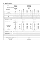
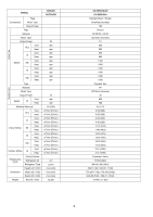
9000 3.6 690 3.82 13.00 92 35 / 28 / 25 51 / - / 48 / - / 63 / - / 3.51 12000 5.7 1.12k 3.12 10.70 96 35 / 28 / 25 51 / - / 50 / - / 65 / - / - CS-E9SD3UAW CU-E9SD3UA ARI Single, 60 Max. 3.00 10200 850 3.53 12.00 - Min. 1.20 4100 250 4.80 16.40 - 4.14 14100 1.50k 2.76 9.40 - 1.20 - Panasonic CS-E18SD3UAW | service manual - Page 6
/min (ft3/min) m3/min (ft3/min) m3/min (ft3/min) m3/min (ft3/min) cm3 g (oz) mm (inch) mm (inch) mm (inch) kg (lb) CS-E9SD3UAW CU-E9SD3UA Hermetic Motor / Rotary Brushless (4-poles) 700 Sirocco GFZ010A / GF20 DC Motor (8-poles) 51 880 800 940 880 1120 1090 1300 1300 1380 1380 - Panasonic CS-E18SD3UAW | service manual - Page 7
°C/°F Minimum °C/°F Maximum °C/°F Minimum °C/°F Dry Bulb 32 / 89.6 16 / 60.8 30 / 86.0 16 / 60.8 46 / 114.8 -17.8 / 0 24 / 75.2 -20 / -4 CS-E9SD3UAW CU-E9SD3UA 6.35 (1/4) / 9.52 (3/8) 7.5 (24.6) 3 (9.8) ~ 20 (65.6) 15 (49.2) 20 (0.2) 7.5 (24.6) 16 / 0.63 117.5 / 4.63 Aluminium (Pre Coat) Slit - Panasonic CS-E18SD3UAW | service manual - Page 8
11500 4.7 920 3.64 12.50 94 35 / 28 / 25 51 / - / 49 / - / 64 / - / 4.05 13800 6.3 1.25k 3.24 11.00 95 35 / 28 / 25 51 / - / 51 / - / 66 / - / - CS-E12SD3UAW CU-E12SD3UA ARI Single, 60 Max. 3.90 13300 1.15k 3.39 11.55 - Min. 1.20 4100 250 4.80 16.40 - 4.77 16300 1.71k 2.79 9.50 - Panasonic CS-E18SD3UAW | service manual - Page 9
/min (ft3/min) m3/min (ft3/min) m3/min (ft3/min) m3/min (ft3/min) cm3 g (oz) mm (inch) mm (inch) mm (inch) kg (lb) CS-E12SD3UAW CU-E12SD3UA Hermetic Motor / Rotary Brushless (4-poles) 700 Sirocco GFZ010A / GF20 DC Motor (8-poles) 51 880 800 940 880 1120 1090 1300 1300 1430 - Panasonic CS-E18SD3UAW | service manual - Page 10
Maximum °C/°F Minimum °C/°F Maximum °C/°F Minimum °C/°F Dry Bulb 32 / 89.6 16 / 60.8 30 / 86.0 16 / 60.8 46 / 114.8 -17.8 / 0 24 / 75.2 -20 / -4 CS-E12SD3UAW CU-E12SD3UA 6.35 (1/4) / 12.70 (1/2) 7.5 (24.6) 3 (9.8) ~ 20 (65.6) 15 (49.2) 20 (0.2) 7.5 (24.6) 16 / 0.63 117.5 / 4.63 Aluminium (Pre Coat - Panasonic CS-E18SD3UAW | service manual - Page 11
17200 8.5 1.58k 3.18 10.85 89 41 / 30 / 27 57 / - / 49 / - / 63 / - / 6.09 20800 9.8 1.83k 3.32 11.35 90 41 / 32 / 29 57 / - / 51 / - / 65 / - / - CS-E18SD3UAW CU-E18SD3UA ARI Single, 60 Max. 5.70 19400 1.82k 3.13 10.65 - Min. 1.70 5800 430 3.95 13.45 - 7.10 24200 2.18k 3.26 11 - Panasonic CS-E18SD3UAW | service manual - Page 12
/min (ft3/min) m3/min (ft3/min) m3/min (ft3/min) m3/min (ft3/min) cm3 g (oz) mm (inch) mm (inch) mm (inch) kg (lb) CS-E18SD3UAW CU-E18SD3UA Hermetic Motor / Rotary Brushless (4-poles) 1.70k Sirocco GFZ010A / GF20 DC Motor (8-poles) 51 920 920 980 1000 1230 1240 1480 1480 1530 - Panasonic CS-E18SD3UAW | service manual - Page 13
Maximum °C/°F Minimum °C/°F Maximum °C/°F Minimum °C/°F Dry Bulb 32 / 89.6 16 / 60.8 30 / 86.0 16 / 60.8 46 / 114.8 -17.8 / 0 24 / 75.2 -20 / -4 CS-E18SD3UAW CU-E18SD3UA 6.35 (1/4) / 12.70 (1/2) 7.5 (24.6) 3 (9.8) ~ 30.5 (100.0) 15 (49.2) 25 (0.3) 10 (32.8) 16 / 0.63 117.5 / 4.63 Aluminium (Pre - Panasonic CS-E18SD3UAW | service manual - Page 14
operation Operation Improvement o Quiet mode to reduce the indoor unit operating sound o Powerful mode to reach the desired room temperature quickly o 24-hour timer setting Serviceability Improvement o Breakdown Self Diagnosis function 14 - Panasonic CS-E18SD3UAW | service manual - Page 15
4. Location of Controls and Components 4.1 Indoor Unit Air outlet Air inlet 4.2 Outdoor Unit Air inlet (rear) Air inlet (side) 4.3 Remote Control Transmitter OFF/ON Powerful operation Operation mode Temperature setting Check Quiet operation Fan speed selection Timer setting Clock setting - Panasonic CS-E18SD3UAW | service manual - Page 16
5. Dimensions 5.1 Indoor Unit (AIR OUTLET DUCT FLANGE) 692 (27 - 1/4) (AIR OUTLET DUCT FLANGE) 145 (5 - 11/16) 26 (1 - 1/32) 5 - Ø 3.1 HOLE 160 X 4 = 640 96 (3 - 25/32) 27 (1 - 1/16) 28 (1-3/32) 2 - Ø 3.1 HOLE 84 (3-5/16) 30 (1-3/16) 10 (3/8) 81 - Panasonic CS-E18SD3UAW | service manual - Page 17
5.2 Outdoor Unit 5.2.1 CU-E9SD3UA CU-E12SD3UA Space necessary for installation 10 cm 10 cm 100 cm 24.4 (15/16) (104.7) (4-3/32) Anchor Bolt Pitch 320 x 570 780 (30-23/32) 570 (22-7/16) 34.5 (1-11/32) 67.6 (2-21/32) 104.9 60.5 (4-1/8) (2-3/8) 84.8 - Panasonic CS-E18SD3UAW | service manual - Page 18
6. Refrigeration Cycle Diagram 6.1 CS-E9SD3UAW CU-E9SD3UA INDOOR INTAKE TEMP. SENSOR HEAT EXCHANGER (EVAPORATOR) PIPE TEMP. SENSOR 1 LIQUID SIDE 2-WAY VALVE PIPE (INLET) TEMP. SENSOR 2 OUTDOOR PROCESS DISCHARGE EXPANSION TUBE - Panasonic CS-E18SD3UAW | service manual - Page 19
6.2 CS-E12SD3UAW CU-E12SD3UA INDOOR OUTDOOR INTAKE TEMP. SENSOR HEAT EXCHANGER (EVAPORATOR) PIPE TEMP. SENSOR 1 LIQUID SIDE 2-WAY VALVE PIPE (INLET) TEMP. SENSOR 2 DISCHARGE EXPANSION MUFFLER - Panasonic CS-E18SD3UAW | service manual - Page 20
6.3 CS-E18SD3UAW CU-E18SD3UA INDOOR OUTDOOR INTAKE TEMP. SENSOR HEAT EXCHANGER (EVAPORATOR) COOLING HEATING PIPE TEMP. SENSOR 1 LIQUID SIDE 2-WAY VALVE EXPANSION RECEIVER VALVE STRAINER PIPE ( - Panasonic CS-E18SD3UAW | service manual - Page 21
7. Block Diagram 7.1 CS-E9SD3UAW CU-E9SD3UA CS-E12SD3UAW CU-E12SD3UA 21 Indoor Unit Outdoor Unit FUSE101 1 FUSE DM SC FM SINGLE PHASE POWER SUPPLY 1 Ø 208/230V 60Hz 2 3 NOISE FILTER PTC2 PTC RY- - Panasonic CS-E18SD3UAW | service manual - Page 22
7.2 CS-E18SD3UAW CU-E18SD3UA 22 Indoor Unit Outdoor Unit SINGLE PHASE POWER SUPPLY AC208 - 230V 60Hz L1 FUSE3 L2 FUSE FUSE2 DB2 NOISE FILTER NTC TH1 - Panasonic CS-E18SD3UAW | service manual - Page 23
8. Wiring Connection Diagram 8.1 Indoor Unit TO OUTDOOR UNIT FUSE T3.15A L250V MOTOR Y B W M BL R DRAIN PUMP Y Y/G M 1 Y GROUNDING TERMINAL 1 BL G 2W 3R TERMINAL BOARD 1 HAJEM-A 4 (WHITE) 7 6 CN-FM 5 (WHITE) 4 1 1 CN-CNT 5 ELECTRONIC (WHITE) CONTROLLER RECTIFICATION CIRCUIT - Panasonic CS-E18SD3UAW | service manual - Page 24
8.2 Outdoor Unit 8.2.1 CU-E9SD3UA CU-E12SD3UA SINGLE PHASE POWER SUPPLY TO INDOOR UNIT L1 YLW/GRN L2 1 2 3 (BLACK) (WHITE) (RED) TERMINAL BOARD BLK BLK WHT RED DATA (RED) WHT AC-BLK (BLK) COMMUNICATION CIRCUIT FUSE101 20A 250V NOISE FILTER CIRCUIT AC-WHT GRN (WHT) FG1 (GRN) GRN - Panasonic CS-E18SD3UAW | service manual - Page 25
8.2.2 CU-E18SD3UA GRN YLW/GRN SINGLE PHASE POWER SUPPLY YLW/GRN GRN L1 L2 TERMINAL TERMINAL BOARD BLK BOARD WHT WHT BLK ACN1 (WHITE) ACL1 (BLACK) FUSE3 (25A, 250V) COM3 (RED) 1 CN-COM (YELLOW) COMMUNICATION 4 CIRCUIT CN-BLK NOISE FILTER (BLACK) CIRCUIT CN-WHT (WHITE) FG1 ( - Panasonic CS-E18SD3UAW | service manual - Page 26
9. Electronic Circuit Diagram 9.1 Indoor Unit TO OUTDOOR UNIT FUSE T3.15A L250V 1 HAJEM-A (WHITE) 4 5V 1 KB C32 0.01u R20 10k KB C38 0.01u R56 10k 5 CN-CNT 5V (WHITE) R90 R82 10k 10k 12V 5V L6 L5 KB C52 1000p 50V KB C66 C56 1000p 50V MOTOR Y B W M BL R DRAIN PUMP Y Y/G M 1 - Panasonic CS-E18SD3UAW | service manual - Page 27
9.2 Outdoor Unit 9.2.1 CU-E9SD3UA CU-E12SD3UA ELECTRO-MAGNETIC COIL (EXPANSION VALVE) M SINGLE PHASE POWER SUPPLY TO INDOOR UNIT CN-STM (WHT) 1 D29 D28 D27 D26 6 13V C80 G2 L1 YLW/GRN L2 1 2 3 (BLACK) (WHITE) (RED) TERMINAL BOARD REACTOR BLK BLK WHT WHT RED DATA (RED) AC-BLK (BLK) - Panasonic CS-E18SD3UAW | service manual - Page 28
9.2.2 CU-E18SD3UA SINGLE PHASE POWER SUPPLY TO INDOOR UNIT L1 L2 TERMINAL TERMINAL BOARD BLK BOARD 1 2 3 YLW/GRN WHT GRN GRN WHT BLK RED ACN1 (WHITE) ACL1 (BLACK) COM3 (RED) 4 3 YLW/GRN PC8 EL816X (X) 2 c Q25 0.1A FUSE3 50V (25A, 250V) RT1N432C 5V e R425 G1 20.0k - Panasonic CS-E18SD3UAW | service manual - Page 29
10. Printed Circuit Board 10.1 Indoor Unit 10.1.1 Main Printed Circuit Board CN-AC CN-DRMTR1 CN-T1 CN-T2 CN-CNT CN-FSW CN-DISP CN-HT 29 CN-FM CN-TH - Panasonic CS-E18SD3UAW | service manual - Page 30
10.2 Outdoor Unit 10.2.1 Main Printed Circuit Board 10.2.1.1 CU-E9SD3UA CU-E12SD3UA CURRENT TRANSFORMER (CT) AC-WHT AC-BLK POWER TRANSISTOR (IPM) CN-HOT CN-TH CN-TANK CN-DCFM DATA 30 - Panasonic CS-E18SD3UAW | service manual - Page 31
10.2.1.2 CU-E18SD3UA POWER TRANSISTOR (IPM) CN-COM AC-WHT CURRENT TRANSFORMER (CT) AC-BLK CN-HOT CN-FM CN-TANK CN-EV CN-TH1 31 - Panasonic CS-E18SD3UAW | service manual - Page 32
10.2.2 CPU Printed Circuit Board 10.2.2.1 CU-E9SD3UA CU-E12SD3UA CN1 CN2 CN3 10.2.3 Noise Filter Printed Circuit Board 10.2.3.1 CU-E18SD3UA ACN1 (WHITE) ACL1 (BLACK) CN-COM 32 - Panasonic CS-E18SD3UAW | service manual - Page 33
11. Installation Instruction IMPORTANT (ONLY FOR E9SD3UAW AND E12SD3UAW) This product has been designed and manufactured to meet ENERGY STAR® criteria (12.7 mm) 1/4" (6.35 mm) 5/8" (15.88 mm) 1/4" (6.35 mm) Pipe size reducer (CZ-MA1P) for outdoor Multi connection CS-E12SD3UAW, CS-E18SD3UAW 33 - Panasonic CS-E18SD3UAW | service manual - Page 34
17200 (12.7 mm) 9.8 ft (3 m) 65.6 ft (20 m) 0.2 oz/ft (20 g/m) 24.6 ft (7.5 m) 0.3 100.0 ft oz/ft (30.5 m) (25 g/m) 32.8 ft (10 m) Example: For E9SD3UAW If the unit is installed at 32.8 ft (10 m) distance, the quantity of additional refrigerant should be 1.64 oz (50 g) .... (32.8 - 24.6) ft - Panasonic CS-E18SD3UAW | service manual - Page 35
location Do not install the unit in excessive oil fume area such as kitchen, workshop and etc. The location should be strong enough to support the main unit without vibration. There should not be any heat or steam source nearby. Drainage should be easy. Avoid locating the drain port - Panasonic CS-E18SD3UAW | service manual - Page 36
Required Minimum Space for Installation and Service 22 7/32" (564) Min. 7 7/8" (200) o r more 32 7/16" (824) (Suspension bolt pitch) Min. 7 7/8" (200) or more Electrical component box Inspection access 17 23/32" x 17 - Panasonic CS-E18SD3UAW | service manual - Page 37
") (60 to 90 mm) Approx. 4 1/2" (144) Hanging bolt M10 Roof beam Ceiling surface Secure the hanging bolts (M10, locally purchased) firmly in a manner capable of supporting the unit weight. Consult your construction or interior contractor for details on finishing the ceiling opening. 37 - Panasonic CS-E18SD3UAW | service manual - Page 38
Installing an Intake and Discharge Duct Type Ensure the range of unit external static pressure is not exceeded. Refer technical manual for the range of external static pressure setting. Connect the duct as shown. When attaching duct to the intake side, remove the product filter frame - Panasonic CS-E18SD3UAW | service manual - Page 39
Mounting Remote Controller Receiver Install the remote controller receiver cable at least 1 31/32" (50 mm) away from electric wires of other appliances to avoid miss-operation (electromagnetic noise). 1 Remove the bottom case. Attention Mounting the bottom case Tighten the screws securely until - Panasonic CS-E18SD3UAW | service manual - Page 40
Connect the indoor unit and the remote control receiver 5. (Refer to the illustration.) Fix the green wire from receiver cable 8 to the grounding location provided inside control board. Receiver cable 8 Control box Remote control receiver 5 11.1.4 Connecting the Drain Piping Lay the drain - Panasonic CS-E18SD3UAW | service manual - Page 41
11.1.6 Connect the Cable to the Indoor Unit Remove control box cover. Remove the plugs. Fix the conduit connections to the knockout holes together with lock nuts, then secure them against the control box side panel. Receiver cable wires 8 must pass through the upper conduit hole. Make sure - Panasonic CS-E18SD3UAW | service manual - Page 42
11.1.6.1 Wire Stripping and Connecting Requirement Wire stripping No loose strand when inserted 13/32" ± 1/32" 10 ± 1 mm Indoor/outdoor connection terminal board 7/32" (5 mm) or more (gap between wires) Conductor Conductor Conductor not fully inserted over inserted fully inserted ACCEPT - Panasonic CS-E18SD3UAW | service manual - Page 43
) Wrench (Adjustable Wrench) Flare Nut (Connection pipe) Female side Applicable to Liquid and Gas side of CS-E9SD3UAW Torque Wrench for Flare Nut Liquid side of CS-E12SD3UAW CS-E18SD3UAW Male side Pipe Size Hall Union Packing Reducer Flare Nut Female side (Auxiliary pipe) (Connection pipe - Panasonic CS-E18SD3UAW | service manual - Page 44
close the low side valve of the charging set and turn off the vacuum pump. 5 Disconnect the vacuum pump house from the service port of the 3-way valve. 6 Tighten the service port caps of the 3-way valve at a torque of 13.3 Ibf•ft (18 N•m) with a torque wrench. 7 Remove the valve caps of - Panasonic CS-E18SD3UAW | service manual - Page 45
Connect the cable to the Outdoor Unit For model E9SD3UAW, E12SD3UAW Top Panel 1 Remove Top panel. 2 Remove original position with the screws. 11 For wire stripping and connection requirement, refer to instruction 11.1.6 of indoor unit. Earth wire longer than other AC wires for safety reasons - Panasonic CS-E18SD3UAW | service manual - Page 46
and control board cover (metal and resin) to the original position with the screws. 11 For wire stripping and connection requirement, refer to instruction 11.1.6 of indoor unit. Terminal Board Earth wire longer than others AC wires for safety reasons Holder Terminal Board Earth wire longer than - Panasonic CS-E18SD3UAW | service manual - Page 47
11.2.6 Piping Insulation 1 Please carry out insulation at pipe connection portion as mentioned in Indoor/Outdoor Unit Installation Diagram. Please wrap the insulated piping end to prevent water from going inside the piping. 2 If drain hose or connecting piping is in the room (where dew may form), - Panasonic CS-E18SD3UAW | service manual - Page 48
by measuring the temperature of the environment and performing temperature shifting. The compressor at outdoor unit is operating following the frequency instructed by the microcomputer at indoor unit that judging the condition according to internal setting temperature and intake air temperature. 12 - Panasonic CS-E18SD3UAW | service manual - Page 49
mode is decided. Heat Maintain Cool/Dry -10.8 -9 -7.2 -5.4 -3.6 -1.8 0 1.8 3.6 5.4 7.2 9 10.8 12.1.6 Indoor Fan Motor Operation A. Basic Rotation Speed (rpm) i. Manual Fan Speed [Cooling, Dry] Fan motor's number of rotation is determined according to remote control setting. Remote Control - Panasonic CS-E18SD3UAW | service manual - Page 50
The indoor fan will operate according to pattern below. Fan Speed Higher a Medium Lower b c d e f [1 pattern : 10 s] g h a b [Heating] According to indoor pipe temperature, automatic heating fan speed is determined as follows. 102ºF RPM Increased RPM Maintain RPM Reduced 95ºF - Panasonic CS-E18SD3UAW | service manual - Page 51
speed is changed from normal setting to quiet setting of respective fan speed. This is to reduce sound of Hi, Me, Lo for 3dB. 2 Manual fan speed for quiet operation is 1 step from setting fan speed. 3 Compressor frequency reduced. 12.2.1 Quiet operation (Heating) A. Purpose To provide quiet heating - Panasonic CS-E18SD3UAW | service manual - Page 52
12.3 Powerful Mode Operation When the powerful mode is selected, the internal setting temperature will shift higher up to +10.8°F (for Heating) or lower up to 7.2°F (for Cooling/Soft Dry) than remote control setting temperature for 20 minutes to achieve the setting temperature quickly. 12.4 Timer - Panasonic CS-E18SD3UAW | service manual - Page 53
12.7 Electric Heater Control 1 Starting condition A) When all condition (1+2+3+4+5+6+7) are fulfilled. 1 Operation ON 2 Indoor Heating mode 3 Thermostat ON 4 Temperature different control (°F) Temp difference (Remote controller setting - Intake air temperature) When air conditioning is switched ON - Panasonic CS-E18SD3UAW | service manual - Page 54
12.8 Electric Heater Control 2 During Error happened, air conditioning unit will stop operation, TIMER LED will blink and indoor vane closed. Electric heater can be switch ON when fulfill the starting condition as follow except 2 errors. o H14 (Indoor intake air temperature sensor abnormality) o - Panasonic CS-E18SD3UAW | service manual - Page 55
cycle and return back to the outdoor unit. 13.1.3 Total Running Current Control 1 When the outdoor unit total running current (AC) exceeds X value, the frequency instructed for compressor operation will be decreased. 2 If the running current does not exceed X value for five seconds, the frequency - Panasonic CS-E18SD3UAW | service manual - Page 56
condition repeats continuously for seven times, all indoor and outdoor relays will be cut off. 13.1.5 Compressor Overheating Prevention Control Instructed frequency for compressor operation will be regulated by compressor top temperature. The changes of frequency are as below figure. If compressor - Panasonic CS-E18SD3UAW | service manual - Page 57
13.2.2 Cooling Overload Control i. Pipe temperature limitation/restriction Detects the Outdoor pipe temperature and carry out below restriction/limitation (Limit the compressor Operation frequency) The compressor stop if outdoor pipe temperature exceeds 145.4°F. If the compressor stops 4 times - Panasonic CS-E18SD3UAW | service manual - Page 58
13.3 Protection Control for Heating Operation 13.3.1 Intake Air Temperature Control Compressor will operate at maximum frequency if below conditions occur: 1 When the indoor intake air temperature is 86°F or above. 13.3.2 Outdoor Air Temperature Control The maximum current value is regulated when - Panasonic CS-E18SD3UAW | service manual - Page 59
13.3.7 Pump Down Operation By CN-S A convenience method to activate pump down operation. Control start condition: o During power standby condition, short CN-S continuously between 1 second and 10 seconds. Control stop condition: o 480 seconds after pump down operation starts. o CN-S is shorted - Panasonic CS-E18SD3UAW | service manual - Page 60
14. Servicing Mode 14.1 TEST RUN OPERATION (FOR PUMP DOWN/SERVICING PURPOSE) The Test Run operation will be activated by short-circuiting CN-S (Pin 1 & 2) at outdoor unit PCB after power supplied to outdoor unit terminal 1 and 2. The unit forced to run rated frequency cooling operation mode. 60 - Panasonic CS-E18SD3UAW | service manual - Page 61
can be used to operate air conditioner with limited function if remote control is misplaced or malfunction. 2 TEST RUN OPERATION (FOR PUMP DOWN/SERVICING PURPOSE) The Test Run operation will be activated if the Auto OFF/ON button is pressed continuously for more than 5 seconds. A "beep" sound - Panasonic CS-E18SD3UAW | service manual - Page 62
14.3 Cooling Only Operation (Single connection Only, Multi connection please refer to Multi outdoor manual) 14.3.1 How to activate and deactivate Cooling Only Operation AUTO SW is pressed 5s 8s 11s 16s 21s 26s 36s Emergency Operation Forced Cooling Operation - Panasonic CS-E18SD3UAW | service manual - Page 63
14.4.2 Control method Heating mode (using remocon function 58) Normal display mode Press SW (t 0secs) Shift -3°C When SW pressed continuously for t 5secs to enter service zone & press SW's to choose function 58 (shift 0°C) Timer Up Down button Shift -1°C Shift 0°C Shift +1°C Shift +3°C Range - Panasonic CS-E18SD3UAW | service manual - Page 64
Cooling or Dry mode (using remocon function 59) Normal display mode Press SW (t 0secs) Shift -3°C When SW pressed continuously for t 5secs to enter service zone & press SW's to choose function 59 (shift 0°C) Timer Up Down button Shift -1°C Shift 0°C Shift +1°C Shift +3°C Range = - Panasonic CS-E18SD3UAW | service manual - Page 65
Filter cleaning enable/disable selection Normal display mode Press SW to enter customer zone & press SW's to choose function 7 Control Disable Control Enable Transmit "Enable or Disable" code 1 Press SW, special setting is immediately cancelled and normal mode starts. 2 If no SW is pressed for - Panasonic CS-E18SD3UAW | service manual - Page 66
Auto restart enable/disable selection Normal display mode Press SW to enter customer zone & press SW's to choose function 10 Control Disable Control Enable Transmit "Enable or Disable" code 1 Press SW, special setting is immediately cancelled and normal mode starts. 2 If no SW is pressed for - Panasonic CS-E18SD3UAW | service manual - Page 67
15. Troubleshooting Guide 15.1 Refrigeration Cycle System In order to diagnose malfunctions, make sure that there are no electrical problems before inspecting the refrigeration cycle. Such problems include insufficient insulation, problem with the power source, malfunction of a compressor and a fan - Panasonic CS-E18SD3UAW | service manual - Page 68
15.2 Relationship Between the Condition of the Air Conditioner and Pressure and Electric Current Condition of the air conditioner Insufficient refrigerant (gas leakage) Clogged capillary tube or Strainer Short circuit in the indoor unit Heat radiation deficiency of the outdoor unit Inefficient - Panasonic CS-E18SD3UAW | service manual - Page 69
15.3 Breakdown Self Diagnosis Function 15.3.1 Self Diagnosis Function (Three Digits Alphanumeric Code) Once abnormality has occurred during operation, the unit will stop its operation, and OFF/ON operation LED OFF. OFF indicator does not shown on remote control display. In operation after - Panasonic CS-E18SD3UAW | service manual - Page 70
15.4 Error Codes Table Diagnosis display Abnormality / Protection control H00 No abnormality detected H11 Indoor/outdoor abnormal communication H12 Connection capability rank abnormal H14 Indoor intake air temperature sensor abnormality H15 Outdoor compressor temperature sensor abnormality - Panasonic CS-E18SD3UAW | service manual - Page 71
Diagnosis display Abnormality / Protection control Abnormality Judgment Emergency Operation Primary location to verify F98 Total running current protection 3 times occurrence within 20 minutes F99 Outdoor Direct Current (DC) peak detection 7 times occurrence continuously Note: "O" - - Panasonic CS-E18SD3UAW | service manual - Page 72
Indoor unit-outdoor unit signal transmission error due to breaking of wire in the connection wires between the indoor and outdoor units. Troubleshooting When abnormality indication starts again Measure the AC voltage at terminal 1 & 2 of outdoor unit terminal board Caution For safety reason and - Panasonic CS-E18SD3UAW | service manual - Page 73
wiring. Indoor-outdoor unit signal transmission error due to breaking of wire 3 in the connection wires between the indoor and outdoor units. Troubleshooting When abnormality indication starts again Check the indoor and outdoor unit connection wires Is there any wiring error? NO Check indoor and - Panasonic CS-E18SD3UAW | service manual - Page 74
intake air temperature sensor are used to determine sensor errors. Malfunction Caused Faulty connector connection. Faulty sensor. Faulty PCB. Troubleshooting When abnormality indication starts again Check the connector connection: ● Turn off the power ● Check the connector connection Is the - Panasonic CS-E18SD3UAW | service manual - Page 75
compressor temperature sensor are used to determine sensor errors. Malfunction Caused Faulty connector connection. Faulty sensor. Faulty PCB. Troubleshooting When abnormality indication starts again Check the connector connection: ● Turn off the power ● Check the connector connection Is the - Panasonic CS-E18SD3UAW | service manual - Page 76
value for 3 minutes. Malfunction Caused Lack of gas Broken CT (current transformer) Broken Outdoor PCB Troubleshooting When abnormality indication starts again Refer to Service Manual Technical Graph for Temp vs Current and Pressure For safety reason and to prevent component Caution - Panasonic CS-E18SD3UAW | service manual - Page 77
stops due to breaking of fan motor lead wires. Operation stops due to Hall IC malfunction. Operation error due to faulty indoor unit PCB. Troubleshooting When abnormality indication starts again Turn off power supply and rotate fan by hand Does fan rotate smoothly? YES Turn power supply on and - Panasonic CS-E18SD3UAW | service manual - Page 78
exchanger temperature sensor are used to determine sensor errors. Malfunction Caused Faulty connector connection. Faulty sensor. Faulty PCB. Troubleshooting When abnormality indication starts again Check the connector connection: ● Plug out connector from the indoor unit PCB ● Measure the - Panasonic CS-E18SD3UAW | service manual - Page 79
exchanger temperature sensor 2 are used to determine sensor errors. Malfunction Caused Faulty connector connection. Faulty sensor. Faulty PCB. Troubleshooting When abnormality indication starts again Check the connector connection: ● Plug out connector from the indoor unit PCB ● Measure the - Panasonic CS-E18SD3UAW | service manual - Page 80
air temperature sensor are used to determine sensor errors. Malfunction Caused Faulty connector connection. Faulty sensor. Faulty PCB. Troubleshooting When abnormality indication starts again Check the connector connection: ● Turn off the power ● Check the connector connection For safety - Panasonic CS-E18SD3UAW | service manual - Page 81
pipe temperature sensor are used to determine sensor errors. Malfunction Caused Faulty connector connection. Faulty sensor. Faulty PCB. Troubleshooting When abnormality indication starts again Check the connector connection: ● Turn off the power ● Check the connector connection Caution For - Panasonic CS-E18SD3UAW | service manual - Page 82
pipe temperature sensor are used to determine sensor errors. Malfunction Caused Faulty connector connection. Faulty sensor. Faulty PCB. Troubleshooting When abnormality indication starts again Check the connector connection: ● Turn off the power ● Check the connector connection Is the - Panasonic CS-E18SD3UAW | service manual - Page 83
. Malfunction Caused Wrong models interconnected. Wrong indoor unit and outdoor unit PCBs used. Indoor unit or outdoor unit PCB defective. Troubleshooting When abnormality indication starts again Check indoor and outdoor units model number For safety reason and to prevent component breakdown - Panasonic CS-E18SD3UAW | service manual - Page 84
stops due to breaking of fan motor lead wires. Operation stops due to Hall IC malfunction. Operation error due to faulty outdoor unit PCB. Troubleshooting When abnormality indication starts again Turn off power supply and rotate fan by hand Does fan rotate smoothly? YES Turn power supply on and - Panasonic CS-E18SD3UAW | service manual - Page 85
often in heating mode. Malfunction Caused Indoor heat exchanger thermistor Clogged air filter or heat exchanger Over-bent pipe (liquid side) Troubleshooting When abnormality indication starts again Check the indoor unit intake air filter Caution For safety reason and to prevent component - Panasonic CS-E18SD3UAW | service manual - Page 86
fan motor Refrigerant shortage (refrigerant leakage) Clogged expansion valve or strainer Faulty indoor pipe temperature sensor Faulty indoor unit PCB Troubleshooting When abnormality indication starts again Check the air passage Is there any short circuit? YES For safety reason and to - Panasonic CS-E18SD3UAW | service manual - Page 87
Indoor heat exchanger (pipe) thermistor 4-way valve malfunction Troubleshooting When abnormality starts again Check the indoor pipe temperature thermistor: Plug thermistor matches the value specified in its characteristic chart? YES Problem occurs in heating mode only? Defect in indoor pipe - Panasonic CS-E18SD3UAW | service manual - Page 88
up the DC level. When DC voltage detected is HIGH (391Vdc - 425Vdc), active LOW signal will send by the controller to turn OFF relay RY-C. Troubleshooting When abnormality indication starts again Reset the error code and turn on the unit again Is AC power supply normal fluctuation? YES Verify PFC - Panasonic CS-E18SD3UAW | service manual - Page 89
is low while the compressor is running at higher than the setting frequency. Malfunction Caused Lack of gas. 3-way valve close. Troubleshooting When F91 indication happens Check 3 way valve Caution For safety reason and to prevent component breakdown, always switch off the power before remove - Panasonic CS-E18SD3UAW | service manual - Page 90
running condition through the position detection circuit. Malfunction Caused Compressor terminal disconnect Faulty Outdoor PCB Faulty compressor Troubleshooting When F93 indication happens Check the U, V and W connector connection: - Turn OFF the power - Check the U, V and W connector - Panasonic CS-E18SD3UAW | service manual - Page 91
rise due to defective outdoor heat exchanger thermistor. Outdoor heat exchanger temperature rise due to defective of outdoor unit PCB. Troubleshooting When abnormality indication starts again Check the outdoor unit installation condition (during cooling or soft dry operation) Is there any - Panasonic CS-E18SD3UAW | service manual - Page 92
of IPM. IPM overheats due to defective IPM temperature sensor. Multi Models Only o Compressor OL connector poor contact. o Compressor OL faulty. Troubleshooting When F96 indication happens Check the outdoor unit installation condition (during cooling or soft-dry operation) Is there any improper - Panasonic CS-E18SD3UAW | service manual - Page 93
Faulty compressor tank temperature sensor 2/3 way valve closed Refrigerant shortage (refrigerant leakage) Faulty outdoor unit PCB Faulty compressor Troubleshooting When F97 indication happens Check the compressor tank temperature sensor. Caution For safety reason and to prevent component - Panasonic CS-E18SD3UAW | service manual - Page 94
current value being detected by current transformer (CT) with the compressor running. Malfunction Caused Excessive refrigerant. Faulty outdoor unit PCB. Troubleshooting When F98 indication happens Get restarted and measure the input current. Caution For safety reason and to prevent component - Panasonic CS-E18SD3UAW | service manual - Page 95
peak due to defective power transistor(s). DC current peak due to defective outdoor unit PCB. DC current peak due to short circuit. Troubleshooting When abnormality indication starts again Reset the error code and turn on the unit again Is there a sound when compressor starts? NO (Compressor - Panasonic CS-E18SD3UAW | service manual - Page 96
16. Disassembly and Assembly Instructions WARNING High Voltage are generated in the electrical parts area by the capacitor. Ensure that the capacitor has discharged sufficiently before proceeding with repair work. - Panasonic CS-E18SD3UAW | service manual - Page 97
1 Detach the Upper and Inner Casing 2 Disengage the 4 catches (2 each on the left and right) on the Air Guide. Air guide (Upper) Air guide (Upper) Catches Air guide (Bottom) Air guide (Bottom) 3 Unscrew the 2 screws on the Fan Motor Bracket and detach Fan Motor Bracket. 4 Remove the Fan Motor - Panasonic CS-E18SD3UAW | service manual - Page 98
2 Unscrew 5 screws on the Evaporator and remove 2 sensor from holder and remove Evaporator from the unit. Remove Screw Remove Sensor 3 Unscrew 4 screws, 1 nut and 1 Spring Clip on the Drain Motor Bracket and remove Drain Motor from unit. Remove Screw Spring Clip Remove Nut 4 Unscrew 3 screws on - Panasonic CS-E18SD3UAW | service manual - Page 99
16.2 Outdoor Electronic Controller Removal Procedure 16.2.1 CU-E9SD3UA CU-E12SD3UA Caution! When handling electronic controller, be careful of electrostatic discharge. 1 Remove the 3 screws of the Top Panel. 5 Remove the Control Board as follows: Fig. 1 2 Remove the 6 screws of the Front Panel. - Panasonic CS-E18SD3UAW | service manual - Page 100
16.2.2 CU-E18SD3UA Caution! When handling electronic controller, be careful of electrostatic discharge. 1 Remove the 8 screws of the Top Panel. 4 Remove the Control Board. Fig. 1 2 Remove the 8 screws of the Front Panel. Fig. 4 5 Remove the 6 screws of the Electronic Controller. Fig. 2 3 Remove - Panasonic CS-E18SD3UAW | service manual - Page 101
, Hi Fan, Cool mode at 60.8°F Voltage: 208V/230V 17.1.1.1 CS-E9SD3UAW/CU-E9SD3UA Indoor (°C/°F) Outdoor DB (°C/°F) DB WB -20 (-4) TC 768 1985 1460 864 (Dry bulb value based on 46% humidity) 17.1.1.2 CS-E12SD3UAW/CU-E12SD3UA Indoor (°C/°F) Outdoor DB (°C/°F) DB WB -20 (-4) TC SHC - Panasonic CS-E18SD3UAW | service manual - Page 102
17.1.1.3 CS-E18SD3UAW/CU-E18SD3UA Indoor (°C/°F) DB WB 27 (80.6) 23 (73.4) 20 (68) 19 (66.2) 22 (71.6) 16 (60.8) 18 (64.4) 13 (55.4) 16 (60.8) TC - Panasonic CS-E18SD3UAW | service manual - Page 103
/230V 17.1.2.1 Indoor (°C/°F) DB 24 (75.2) 20 (68) 16 (60.8) CS-E9SD3UAW/CU-E9SD3UA -20 (-4) TC IP 2068 1301 2178 1295 1759 1261 -8.3 (17 4601 1369 17.1.2.2 Indoor (°C/°F) DB 24 (75.2) 20 (68) 16 (60.8) CS-E12SD3UAW/CU-E12SD3UA -20 (-4) TC IP 2383 1625 2510 1664 2026 1654 -8.3 (17 - Panasonic CS-E18SD3UAW | service manual - Page 104
length, Hi Fan, Cool mode at 60.8°F Voltage: 208V/230V 17.2.1.1 CS-E9SD3UAW/CU-E9SD3UA Indoor (°C/°F) DB WB -20 (-4) TC SHC IP 27 (80 1707 695 1920 1330 847 (Dry bulb value based on 46% humidity) 17.2.1.2 CS-E12SD3UAW/CU-E12SD3UA Indoor (°C/°F) DB WB -20 (-4) TC SHC IP 27 (80.6) - Panasonic CS-E18SD3UAW | service manual - Page 105
17.2.1.3 CS-E18SD3UAW/CU-E18SD3UA Indoor (°C/°F) DB WB 27 (80.6) 23 (73.4) 20 (68) 19 (66.2) 22 (71.6) 16 (60.8) 18 (64.4) 13 (55.4) 16 (60.8) TC - Panasonic CS-E18SD3UAW | service manual - Page 106
/230V 17.2.2.1 Indoor (°C/°F) DB 24 (75.2) 20 (68) 16 (60.8) CS-E9SD3UAW/CU-E9SD3UA -20 (-4) TC IP 1275 747 1344 736 1085 718 -8.3 (17 4059 1071 17.2.2.2 Indoor (°C/°F) DB 24 (75.2) 20 (68) 16 (60.8) CS-E12SD3UAW/CU-E12SD3UA -20 (-4) TC IP 1472 833 1550 822 1251 802 -8.3 (17 - Panasonic CS-E18SD3UAW | service manual - Page 107
17.3 Fan Performance 17.3.1 CS-E9SD3UAW CU-E9SD3UA Test Report RPM 1500 1300 1120 Static Pressure (Pa) (Inch H2O) -0.1 (-0.0004) 7.7 (0.0309) 28.4 (0.1141) 44.9 (0.1804) 59.0 (0.2371) 70.3 (0.2825) -0.1 (-0.0004) 13.7 (0. - Panasonic CS-E18SD3UAW | service manual - Page 108
17.3.2 CS-E12SD3UAW CU-E12SD3UA Test Report RPM 1550 1300 1120 Static Pressure (Pa) (Inch H2O) -0.1 (-0.0004) 7.7 (0.0309) 28.4 (0.1141) 44.9 (0.1804) 59.0 (0.2371) 70.3 (0.2825) -0.1 (-0.0004) - Panasonic CS-E18SD3UAW | service manual - Page 109
17.3.3 CS-E18SD3UAW CU-E18SD3UA Test Report RPM 1650 1480 1240 Static Pressure (Pa) (Inch H2O) -0.1 (-0.0004) 70.7 (0.2841) 86.6 (0.3480) 98.5 (0.3958) 108.2 (0.4348) 114.9 (0.4617) -0.1 (-0. - Panasonic CS-E18SD3UAW | service manual - Page 110
18. Service Data Service data provided are based on the air conditioner running under rated frequency during forced cooling / forced heating mode. 18.1 Cool Mode Outdoor Air Temperature Characteristic 18.1.1 CS-E9SD3UAW CU-E9SD3UA Condition Indoor room temperature: 80.1°F Dry Bulb/66.9°F Wet Bulb - Panasonic CS-E18SD3UAW | service manual - Page 111
18.1.2 CS-E12SD3UAW CU-E12SD3UA Condition Indoor room temperature: 80.1°F Dry Bulb/66.9°F Wet Bulb Unit setting: Standard piping length, forced cooling at 60.8°F, Hi fan Compressor - Panasonic CS-E18SD3UAW | service manual - Page 112
18.1.3 CS-E18SD3UAW CU-E18SD3UA Condition Indoor room temperature: 80.1°F Dry Bulb/66.9°F Wet Bulb Unit setting: Standard piping length, forced cooling at 60.8°F, Hi fan Compressor - Panasonic CS-E18SD3UAW | service manual - Page 113
18.2 Heat Mode Outdoor Air Temperature Characteristic 18.2.1 CS-E9SD3UAW CU-E9SD3UA Condition Indoor room temperature: 68°F Dry Bulb/ -°F Wet Bulb Unit setting: Standard piping length, forced heating at 86°F, Hi fan Compressor frequency: Rated - Panasonic CS-E18SD3UAW | service manual - Page 114
18.2.2 CS-E12SD3UAW CU-E12SD3UA Condition Indoor room temperature: 68°F Dry Bulb/ -°F Wet Bulb Unit setting: Standard piping length, forced heating at 86°F, Hi fan Compressor frequency: - Panasonic CS-E18SD3UAW | service manual - Page 115
18.2.3 CS-E18SD3UAW CU-E18SD3UA Condition Indoor room temperature: 68°F Dry Bulb/ -°F Wet Bulb Unit setting: Standard piping length, forced heating at 86°F, Hi fan Compressor frequency: - Panasonic CS-E18SD3UAW | service manual - Page 116
Length Correction Factor The characteristic of the unit has to be corrected in accordance with the piping length. 18.3.1 Cooling Capacity 18.3.1.1 CS-E9SD3UAW CU-E9SD3UA CS-12SD3UAW CU-12SD3UA Capacity Correction Factor 1.04 1.03 1.02 1.01 1.00 0.99 0.98 0.97 0.96 0.95 0 2 4 6 8 10 12 14 16 - Panasonic CS-E18SD3UAW | service manual - Page 117
18.3.2 Heating Capacity Capacity Correction Factor 18.3.2.1 1.08 1.06 1.04 1.02 1.00 0.98 CS-E9SD3UAW CU-E9SD3UA CS-12SD3UAW CU-12SD3UA 3 (9.8) 5 (16.4) 7.5 (24.6) 10 (32.8) 15 (49.2) 0.96 0.94 0 2 4 6 8 10 12 14 16 (6.6) (13.1) (19.7) (26.2) (32.8) (39.4) (45.9) (52.5) Pipe Length (m/ft - Panasonic CS-E18SD3UAW | service manual - Page 118
38 37 Note: The above exploded view is for the purpose of parts disassembly and replacement. The non-numbered parts are not kept as standard service parts. 31 32 35 33 36 8 41 42 118 - Panasonic CS-E18SD3UAW | service manual - Page 119
- COMPLETE REMOTE CONTROL COMPLETE ACCESSORY - COMPLETE (RECEIVER) OPERATING INSTRUCTION INSTALLATION INSTRUCTION INSTALLATION INSTRUCTION QTY. CS-E9SD3UAW CS-E12SD3UAW CS-E18SD3UAW REMARK 1 CWE03C1169 ← 1 ACXG07C00070 ← 1 CWG07C1092 ← 1 CWG07C1093 ← 1 CWD531059 ← 1 CWE04C1565 - Panasonic CS-E18SD3UAW | service manual - Page 120
35 44 Note: The above exploded view is for the purpose of parts disassembly and replacement. The non-numbered parts are not kept as standard service parts. 120 - Panasonic CS-E18SD3UAW | service manual - Page 121
SAFETY REF NO. 1 2 3 4 5 6 7 8 9 10 11 12 13 14 15 16 17 19 20 21 22 23 24 25 26 27 28 29 30 31 32 33 34 35 36 37 38 39 40 41 42 43 44 DESCRIPTION & NAME CHASSY ASSY SOUND PROOF MATERIAL (TOP) FAN MOTOR BRACKET SCREW - BRACKET FAN MOTOR FAN MOTOR SCREW - FAN MOTOR MOUNT PROPELLER FAN ASSY NUT - - Panasonic CS-E18SD3UAW | service manual - Page 122
1 24 51 Note: The above exploded view is for the purpose of parts disassembly and replacement. The non-numbered parts are not kept as standard service parts. 122 26 25 - Panasonic CS-E18SD3UAW | service manual - Page 123
SAFETY REF NO. 1 2 3 4 5 9 10 11 12 13 14 15 16 17 19 21 22 23 24 25 26 27 28 29 30 32 33 35 36 37 38 40 41 42 43 44 46 47 48 49 50 51 53 54 DESCRIPTION & NAME CHASSY ASSY ANTI - VIBRATION BUSHING PACKING COMPRESSOR NUT - COMPRESSOR MOUNT FAN MOTOR BRACKET FAN MOTOR SCREW - BRACKET FAN MOTOR SCREW - Panasonic CS-E18SD3UAW | service manual - Page 124
SAFETY REF NO. 56 57 DESCRIPTION & NAME ELECTRONIC CONTROLLER (NOISE FILTER) CLIP FOR SENSOR QTY. 1 1 CU-E18SD3UA CWA748363 CWH711010 (NOTE) All parts are supplied from PAPAMY, Malaysia (Vendor Code: 00029488). "O" marked parts are recommended to be kept in stock. REMARK [PAPAMY] Printed
-
 1
1 -
 2
2 -
 3
3 -
 4
4 -
 5
5 -
 6
6 -
 7
7 -
8
-
9
-
10
-
11
-
12
-
13
-
14
-
15
-
16
-
17
-
18
-
19
-
20
-
21
-
22
-
23
-
24
-
25
-
26
-
27
-
28
-
29
-
30
-
31
-
32
-
33
-
34
-
35
-
36
-
37
-
38
-
39
-
40
-
41
-
42
-
43
-
44
-
45
-
46
-
47
-
48
-
49
-
50
-
51
-
52
-
53
-
54
-
55
-
56
-
57
-
58
-
59
-
60
-
61
-
62
-
63
-
64
-
65
-
66
-
67
-
68
-
69
-
70
-
71
-
72
-
73
-
74
-
75
-
76
-
77
-
78
-
79
-
80
-
81
-
82
-
83
-
84
-
85
-
86
-
87
-
88
-
89
-
90
-
91
-
92
-
93
-
94
-
95
-
96
-
97
-
98
-
99
-
100
-
101
-
102
-
103
-
104
-
105
-
106
-
107
-
108
-
109
-
110
-
111
-
112
-
113
-
114
-
115
-
116
-
117
-
118
-
119
-
120
-
121
-
122
-
123
-
124
 |
 |

© Panasonic Corporation 2016
Order No: PAPAMY1604052CE
Indoor Unit
Outdoor Unit
CS-E9SD3UAW
CS-E12SD3UAW
CS-E18SD3UAW
CU-E9SD3UA
CU-E12SD3UA
CU-E18SD3UA
Destination
USA
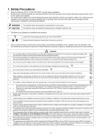
This service information is designed for experienced repair technicians only and is not designed for use by the general public.
It does not contain warnings or cautions to advise non-technical individuals of potential dangers in attempting to service a product.
Products powered by electricity should be serviced or repaired only by experienced professional technicians. Any attempt to service
or repair the product or products dealt with in this service information by anyone else could result in serious injury or death.
WARNING
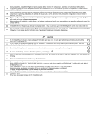
PRECAUTION OF LOW TEMPERATURE
In order to avoid frostbite, be assured of no refrigerant leakage during the installation or repairing of refrigerant circuit.