Panasonic FV08VF2 Installation Instructions
Panasonic FV08VF2 Manual
 |
View all Panasonic FV08VF2 manuals
Add to My Manuals
Save this manual to your list of manuals |
Panasonic FV08VF2 manual content summary:
- Panasonic FV08VF2 | Installation Instructions - Page 1
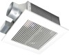
INSTRUCTIONS Ventilating Fan FV-05VF2 FV-08VF2 FV-11VF2 Panasonid READ AND SAVE THESE INSTRUCTIONS. Please read these instructions carefully before attempting to install, operate or service the Panasonic Ventilating Fan. Failure to comply with instructions Guide to Installation Product Service - Panasonic FV08VF2 | Installation Instructions - Page 2
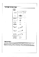
SUPPLIED ACCESSORIES FV-05VF2 FV-08VF2 FV-11VF2 Part name Appearance Quantity Grille r-" 1 Long screw (ST4.2X20) 0 6 Thumb screw ( Panasonic ventilation fans models use a sirocco fan with dolphin-shaped blades driven by a capacitor motor. The motor is designed to have an extended service - Panasonic FV08VF2 | Installation Instructions - Page 3
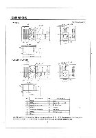
(4 .5) Unit: inches (mm) (25) 10 9 4 3/8 (110) 11 6 5/8 (141) 12 10 1/4 (261) 16 1/8 (410) FV-08VF2 FV-11VF2 0 O 3 4 3 5/8 (92) 1 (25) 1 3/4 (43.5) (25) 10 9 11 7/8 (301) 0 8 7 ® 9 Suspension bracket 10 Junction box 11 Damper 12 Fan body 13 Bracket cover (For 16 inches on center - Panasonic FV08VF2 | Installation Instructions - Page 4
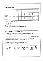
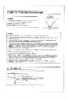
(inches) (sones) (W) (rpm) FV-05VF2 3 0.5 4 0.4 3 0.8 FV-08VF2 Exhaust 120 60 4 0.8 FV-11VF2 3 1.5 4 1.5 Specifications are Do not install this ventilating fan where interior room temperature may exceed 104°F (40°C). 2. Make sure that the electric service supply voltage is 120 V, - Panasonic FV08VF2 | Installation Instructions - Page 5
wiring and other hidden utilities. E. Ducted fans must always be vented to the outdoors. F. These models are UL listed for tub and shower enclosures. G. Before servicing or cleaning unit, switch power off at service panel and lock the service disconnecting means to prevent power from being switched - Panasonic FV08VF2 | Installation Instructions - Page 6
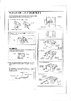
to adaptor by using thumb screw, (Fig. 1) Connection method for 3 Inches adaptor connector • e Duct tape 0 3 inches adaptor connector O 0 4-4 Orifice cover Thumb screw I Fan body Fig. 1 A Press and hold the claw of orifice cover to open the orifice cover. ® .. -.0 ..• Orifice cover Claw - Panasonic FV08VF2 | Installation Instructions - Page 7
suspension bracket to joists by using long screws (ST4.2X20) and secure it to the fan body by using screw II (ST4.2X10) (Fig. 4) 5. Remove junction box diagram (page 5). Using wire nuts, connect house power wires to ventilating fan wires: black to black; white to white; green to green; Replace the - Panasonic FV08VF2 | Installation Instructions - Page 8
should be aligned with the edge of the flange. (Fig. 6) 107/8(27 9. Insert mounting springs into slots as shown and mount grille to fan body. (Fig. 7) 7 Ceiling inches (mm) Slot (irk \ \ Fig. 6 Mounting spring Note: Suitable for use with solid-state speed controls. Solid-state speed controls - Panasonic FV08VF2 | Installation Instructions - Page 9
screw and plug connector to receptacle (Fig, 10) 7. Secure the suspension bracket to joists by using long screws (ST4.2X20) and secure it to fan body by using screw It(ST4,2X10) in vertical direction (Fig. 11) 8. Follow step 8 to 9 of Installation I (page 8) to complete the installation work. When - Panasonic FV08VF2 | Installation Instructions - Page 10
by using thumb screw. (Fig.1 of page 6) 2. Insert the suspension bracket into the bracket cover of adaptor side and the back of the fan body. (Fig.15) (select the suspension bracket according to spacing A as shown below) A A___ /L._ 16 Inches and 19,2 f inches horizontal joist e.-. and /4' 19 - Panasonic FV08VF2 | Installation Instructions - Page 11
is level and square Joists (perpendicular) with the joists.(Fig. 16) Keep the distance B (7/8 inch, 21.6mm) for the thickness of ceiling board. j Fan body Adaptor Junction box 4. Secure the suspension bracket to joists by using long screws (ST4.2X20) (Fig. 17, Fig. 18) A 13 1/4-153/4 (336 - Panasonic FV08VF2 | Installation Instructions - Page 12
body to adaptor by using thumb screw. (Fig. 1 of Joist page 6) 2. Install header between joists by using nails or screws. 0 7 (27s 3. Install the fan body and secure it by using long screws (ST4.2X20) (Fig. 19, Fig. 20) 4. Follow step 5 to 9 of installation I (page 7, page 8) to complete the - Panasonic FV08VF2 | Installation Instructions - Page 13
on unit, Routine maintenance must be done every year. CAUTION: 1, Never use petrol, benzene, thinner or any other such chemicals for cleaning the ventilating fan. 2. Do not damp water to enter motor. 3. Do not soak resin parts in water over 60°C. Gloves Grille 1. Remove grille. (Squeeze mounting - Panasonic FV08VF2 | Installation Instructions - Page 14
fill or batt insulation can be placed directly over the fan housing in the attic. Panasonic fans and fan/light combination units do not create excessive heat that is a common problem with recessed light fixtures or some competitors' fan/light combinations. Our efficient, cool-running motors and our - Panasonic FV08VF2 | Installation Instructions - Page 15
PANASONIC CONSUMER ELECTRONICS COMPANY Division of Panasonic Corporation of North America, One Panasonic Way, Secaucus, NJ 07094 PANASONIC CANADA INC. 5770 Ambler Driver, Mississauga, ON L4W 2T3 www.panasonic.com X0206-8199 08VF24020E
-
 1
1 -
 2
2 -
 3
3 -
 4
4 -
 5
5 -
 6
6 -
 7
7 -
8
-
9
-
10
-
11
-
12
-
13
-
14
-
15
 |
 |

INSTALLATION
INSTRUCTIONS
Ventilating
Fan
FV-05VF2
FV-08VF2
FV-11VF2
Panasonid
READ
AND
SAVE
THESE
INSTRUCTIONS.
Please
read
these
instructions
carefully
before
attempting
to
install,
operate
or
service
the
Panasonic
Ventilating
Fan.
Failure
to
comply
with
instructions
could
result
in
personal
injury
and/or
property
damage.
Please
retain
this
booklet
for
future
reference.
Table
of
Contents
Supplied
Accessories
2
Description
2
Dimensions
3
Specifications
4
Unpacking
4
General
Safety
Information
4-5
Wiring
Diagram
5
Installation
I
(
Joist
Mounting
-I
)
6-8
Installation
II
(
Joist
Mounting
-II
)
8-9
Install
tion
II
I
(
I
-Joist
Mounting
)
10
Installation
IV(
Between
Joist
Mounting
)
10-11
Installation
V
(
Wooden
Header
)
12
Installation
VI
(
In
Existing
Construction
)
12
Maintenance
13
Practical
Guide
to
Installation
14
Product
Service
14