Panasonic KX-TAW84868 Installation Manual
Panasonic KX-TAW84868 - Extension Caller Id Card Manual
 |
UPC - 037988850976
View all Panasonic KX-TAW84868 manuals
Add to My Manuals
Save this manual to your list of manuals |
Panasonic KX-TAW84868 manual content summary:
- Panasonic KX-TAW84868 | Installation Manual - Page 1
Advanced Hybrid & Wireless PBX Installation Manual Model No. KX-TAW848 Thank you for purchasing a Panasonic Advanced Hybrid & Wireless PBX. Please read this manual carefully before using this product and save this manual for future use. KX-TAW848: MPR Version 2.0 SD Logo is a trademark. - Panasonic KX-TAW84868 | Installation Manual - Page 2
Available Proprietary Telephones The PBX supports Panasonic KX-T7000 and KX-TD7000 series telephones: • Analog proprietary telephones (e.g., KX-T7730) • Portable stations (e.g., KX-TD7690) • DSS consoles (e.g., KX-T7740) Note The PBX does not support the following telephones: • Digital proprietary - Panasonic KX-TAW84868 | Installation Manual - Page 3
Abbreviations in this manual Analog proprietary telephone: APT Portable station: PS Single line telephone: SLT Installation Manual 3 - Panasonic KX-TAW84868 | Installation Manual - Page 4
to the operating instructions. Adjust only the controls that are explained in the operating instructions. Improper adjustment of other controls may result in damage and may require service by a qualified use a telephone in the vicinity of a gas leak to report the leak. 4 Installation Manual - Panasonic KX-TAW84868 | Installation Manual - Page 5
SAVE THESE INSTRUCTIONS Installation Manual 5 - Panasonic KX-TAW84868 | Installation Manual - Page 6
Precaution WARNING DO NOT REMOVE SD MEMORY CARD WHILE POWER IS SUPPLIED TO THE ADVANCED HYBRID & WIRELESS PBX Doing so may cause the PBX to fail to start when you restart the system. 6 Installation Manual - Panasonic KX-TAW84868 | Installation Manual - Page 7
SLTs operate properly, there may be a problem with your PBX. Do not reconnect the PBX to the CO lines until it has been serviced by an authorized Panasonic Factory Servicenter. • Wipe the unit with . DISPOSE OF USED BATTERIES ACCORDING TO THE MANUFACTURER'S INSTRUCTIONS. Installation Manual 7 - Panasonic KX-TAW84868 | Installation Manual - Page 8
equipped to make repairs. Product Service Panasonic Factory Servicenters for this product are listed in the servicenter directory. Consult your dealer for detailed instructions. For Future Reference Please print OF PURCHASE NAME OF DEALER DEALER'S ADDRESS DEALER'S TEL. NO. 8 Installation Manual - Panasonic KX-TAW84868 | Installation Manual - Page 9
on the PBX and telephone troubleshooting. About the Other Manuals Along with this Installation Manual, the following manuals are available: Feature Guide Describes all basic, optional and programmable features of the PBX, and step-by-step instruction for performing system programming using - Panasonic KX-TAW84868 | Installation Manual - Page 10
: • Telephone numbers to which the system will be connected • Make: Panasonic • Model: KX-TAW848 • Certification No.: found on the side of the unit • Ringer Equivalence No.: 0.3A • Facility Interface Code: 02LS2 • Service Order Code: 9.0F • Required Network Interface Jack: RJ11 2. Ringer Equivalence - Panasonic KX-TAW84868 | Installation Manual - Page 11
can radiate radio frequency energy and, if not installed and used in accordance with the instructions, may cause harmful interference to radio communications. However, there is no guarantee that interference in the off-peak hours, such as early morning hours or late evenings. Installation Manual 11 - Panasonic KX-TAW84868 | Installation Manual - Page 12
and used in accordance with the instructions, may cause harmful interference to installed and operated in accordance with provided instructions and a minimum 20 cm (8 in) in health care facilities if any regulations posted in the area instruct you not to do so. Hospitals or health care facilities may - Panasonic KX-TAW84868 | Installation Manual - Page 13
Frame Ground Connection 34 2.2.6 Installing/Removing the Optional Service Cards 35 2.2.7 Types of Connectors ...43 2.2.8 Wall Mounting (KX-TAW848 44 2.2.9 Wall Mounting (AC Adaptor 47 2.2. of 2.4 GHz Portable Stations 69 2.7.1 Overview ...69 2.7.2 Procedure Overview ...70 Installation Manual 13 - Panasonic KX-TAW84868 | Installation Manual - Page 14
3 Guide for the PC Programming Software 103 3.1 Overview ...104 3.1.1 Overview ...104 3.2 Connection ...105 3.2.1 Connection ...105 3.3 Installation of the PC Programming Software 107 3.3.1 Installing and Starting the KX-TAW848 Maintenance Console 107 4 Troubleshooting 111 4.1 Troubleshooting - Panasonic KX-TAW84868 | Installation Manual - Page 15
Section 1 System Outline This section provides general information on the PBX, including the system capacity and specifications. Installation Manual 15 - Panasonic KX-TAW84868 | Installation Manual - Page 16
be connected to the PBX to provide Voice Mail (VM) and Automated Attendant (AA) services. A Panasonic VPS which supports DPT (Digital) Integration can be connected to the PBX effortlessly and with minimal setup required. make calls as if they were using their wired telephones. 16 Installation Manual - Panasonic KX-TAW84868 | Installation Manual - Page 17
1.2.1 Main Unit The main unit is equipped with 4 analog trunk ports (one LCOT4 card) and 4 extension ports (Hybrid Ports). For system expansion, optional service cards can be installed. Construction of Main Unit LCOT4 card (installed by default) Front Cover Main Board Cable Cover Installation - Panasonic KX-TAW84868 | Installation Manual - Page 18
& Door Opener BGM/Music On Hold (MOH) Pager/ Amplifier Speaker Wireless Phone PS CS SLT APT DSS Console Fax Machine Voice Processing System 18 Installation Manual - Panasonic KX-TAW84868 | Installation Manual - Page 19
Message Detail Recording (SMDR) PC PLC8 (KX-TAW84876) PLC4 (KX-TAW84875) DPH4 (KX-TAW84861) ECHO8 (KX-TAW84866) EXT-CID (KX-TAW84868) MSG2 (KX-TAW84891) RMT (KX-TAW84896) 4 Hybrid Ports*2 SLT Wireless Phone installed by default. *2 The PBX has 4 Hybrid Ports pre-installed. Installation Manual 19 - Panasonic KX-TAW84868 | Installation Manual - Page 20
KX-TAW84866 8-Channel Echo Canceller 8-channel card for echo cancellation during Card (ECHO8) conferences. KX-TAW84868 KX-TAW84891 2-Channel Message Card 2-channel message card. (MSG2) KX- KX-TAW84896 Remote Card (RMT) Analog modem card for remote communication with the PBX. ITU-T V.90 support - Panasonic KX-TAW84868 | Installation Manual - Page 21
115.2 kbps) 1 Extension Connection Cable SLT 1-pair wire (T, R) APT 2-pair wire (T, R, D1, D2) DSS Console 1-pair wire (D1, D2) CS 1-pair wire (D1, D2) Installation Manual 21 - Panasonic KX-TAW84868 | Installation Manual - Page 22
1.4 Specifications Dimension Weight (when fully mounted) 275 mm (W) × 376 mm (H) × 117 mm (D) (10-4/5 in × 14-4/5 in × 4-3/5 in) Under 3.5 kg (7.72 lb) 22 Installation Manual - Panasonic KX-TAW84868 | Installation Manual - Page 23
. For the connection diagram, refer to "2.5.1 DPH4 Card". The PBX detects input from the sensor when the signal is under 100 Ω. 600 Ω 10 000 Ω Installation Manual 23 - Panasonic KX-TAW84868 | Installation Manual - Page 24
some cards will be ignored. Maximum Terminal Equipment The following number of items of terminal equipment can be supported by the PBX. Terminal Equipment Type SLT APT DSS console CS PS VPS SLT, PT, DSS console, to the PBX that exceed the system capacity will not function. 24 Installation Manual - Panasonic KX-TAW84868 | Installation Manual - Page 25
Section 2 Installation This section describes the procedures to install the PBX. Detailed instructions for planning the installation site, installing the optional service cards, and cabling of peripheral equipment are provided. Further information on system expansion and peripheral equipment - Panasonic KX-TAW84868 | Installation Manual - Page 26
9. Do not stack up the optional service cards. To avoid damage to the optional service cards, always use the extension bolts. Wiring Precautions Be sure to follow these instructions when wiring the unit: 1. Do not equipment may hamper system performance or interrupt the system. 26 Installation Manual - Panasonic KX-TAW84868 | Installation Manual - Page 27
copper conductors with minimum 24 gauge that comply with the electrical specifications for Category 3 wiring as detailed in ANSI/EIA/TIA570A Building Wiring Standards. Installation Manual 27 - Panasonic KX-TAW84868 | Installation Manual - Page 28
5 Mini Plug (for pager and music source) 2 SD Memory Card 1 Main Strap 1 Strap (for the pre-installed LCOT4 card) 1 Optional Card Label Sheet 1 28 Installation Manual - Panasonic KX-TAW84868 | Installation Manual - Page 29
2.2.2 Names and Locations Ground Terminal DC IN 1 Power Switch 2.2 Installation of the PBX SD Memory Card Slot Cover Reset Button System Initialize Switch MOH port Pager port Hybrid Ports RS-232C port USB port Installation Manual 29 - Panasonic KX-TAW84868 | Installation Manual - Page 30
. 1 Slide Button Cable Cover 2. Remove the three screws. Screw 3. Holding the protrusions on both sides of the front cover, swing the cover open. 30 Installation Manual - Panasonic KX-TAW84868 | Installation Manual - Page 31
as shown below. Attaching the Front Cover Fit the front cover to the main unit as shown below, and then close the front cover. Installation Manual 31 - Panasonic KX-TAW84868 | Installation Manual - Page 32
swing the cable cover closed so that the front hooks fit in place. Cable Cover 3. Slide the cable cover down until it locks. 32 Installation Manual - Panasonic KX-TAW84868 | Installation Manual - Page 33
. Note If you need to remove the SD Memory Card: LED Indications Indication SD ACCESS Color Green Description SD memory card status • ON: Accessing Installation Manual 33 - Panasonic KX-TAW84868 | Installation Manual - Page 34
. A reading of less than 1 ohm should be obtained. If the reading is not obtained, the outlet is not adequately grounded. See qualified electrician. 34 Installation Manual - Panasonic KX-TAW84868 | Installation Manual - Page 35
/Removing the Optional Service Cards Slot Position table shows the slot condition. " " indicates that the slot supports the optional service card. Type LCOT4 HLC4 PLC4 SLC8 PLC8 DPH4 ECHO8 EXT-CID service cards. To discharge static electricity, touch ground or wear an grounding - Panasonic KX-TAW84868 | Installation Manual - Page 36
be in the off position. Installing Optional Service Cards 1. Before installing the optional service cards, cut and remove the appropriate card fits over the extension bolt. Optional Service Card 1 2 Extension Bolt CAUTION When installing the optional service cards, do not put pressure on any parts - Panasonic KX-TAW84868 | Installation Manual - Page 37
CO Line Cards" and "2.4 Installation of the Extension Cards". Note Make sure to connect cables after installing the card in the PBX, not before. Installation Manual 37 - Panasonic KX-TAW84868 | Installation Manual - Page 38
2.2 Installation of the PBX 6. Repeat the procedure for other cards. • When installing a card in Slot 11, tighten the card using the screw included with the card, instead of the extension bolt. Screw 38 Installation Manual - Panasonic KX-TAW84868 | Installation Manual - Page 39
2.2 Installation of the PBX Handling of the Cables 1. Attach the strap included with the card to one of the connected cables. Strap 2. Bind all the connected cables together using the strap. 3. Repeat the procedure for other cards. Installation Manual 39 - Panasonic KX-TAW84868 | Installation Manual - Page 40
2.2 Installation of the PBX 4. Attach the main strap (included with the PBX) to any of the 5 rails depending on your preference. 2 1 Main Strap 40 Installation Manual - Panasonic KX-TAW84868 | Installation Manual - Page 41
, you can cut the other side of the cable cover and run the cables through that opening. For safety reasons, smooth the cut edges. Installation Manual 41 - Panasonic KX-TAW84868 | Installation Manual - Page 42
the Optional Service Cards 1. Loosen the extension bolt. 2. Holding the protrusions of the card, pull the card in the direction of the arrows. CAUTION When removing the optional service cards, do not put pressure on any parts of the main board. Doing so may result in damage. 42 Installation Manual - Panasonic KX-TAW84868 | Installation Manual - Page 43
Used for 4 1 • DPH4 (TAW84861) • HLC4 (TAW84871) • SLC8 (TAW84874) • PLC4 (TAW84875) • PLC8 (TAW84876) • LCOT4 (TAW84880) • Hybrid Ports (Main Board) • DPH4 (KX-TAW84861) 1 8 RS-232C 1 1 10 • Main Board 5 USB Mini Plug 6 9 2 1 3 4 + - • Main Board • Main Board (Pager port, MOH port - Panasonic KX-TAW84868 | Installation Manual - Page 44
2.2 Installation of the PBX 2.2.8 Wall Mounting (KX-TAW848) Mounting on Wooden Wall 1. Place the reference for wall mounting on the wall to mark the three screw positions. 130 mm the openings on the back of the cabinet will not be blocked. Be careful not to drop the cabinet. 44 Installation Manual - Panasonic KX-TAW84868 | Installation Manual - Page 45
(1-1/8 in) 6.4 mm (1/4 in) 3. Install the screws (included) in the wall. Drive the screw to this position. 4. Hook the main unit on the screw heads. Installation Manual 45 - Panasonic KX-TAW84868 | Installation Manual - Page 46
of obstacles, so that the openings on the back of the cabinet will not be blocked. Be careful not to drop the cabinet. 46 Installation Manual - Panasonic KX-TAW84868 | Installation Manual - Page 47
. • Install the screws perpendicular to the wall. 3. Hook the AC adaptor on the screw heads. Note Be careful not to drop the AC adaptor. Installation Manual 47 - Panasonic KX-TAW84868 | Installation Manual - Page 48
. Drive the screw to this position. 4. Hook the AC adaptor on the screw heads. Note Be careful not to drop the AC adaptor. 48 Installation Manual - Panasonic KX-TAW84868 | Installation Manual - Page 49
size of this page. If the dimension of the paper output still deviates slightly from the measurement indicated here, use the measurement indicated here. Installation Manual 49 - Panasonic KX-TAW84868 | Installation Manual - Page 50
Line CO Line CO Line Surge Protector Terminal Board Extn. PBX Ground Extn. Extn. Extn. SLT APT CS Frame Ground Extn.: Extension line 50 Installation Manual - Panasonic KX-TAW84868 | Installation Manual - Page 51
extension and CS is different from that for a CO line. Installation of a Ground Rod Surge Protector CO Line Grounding Wire PBX (Underground) Ground Rod Installation Manual 51 - Panasonic KX-TAW84868 | Installation Manual - Page 52
. Notes • • The above figures are recommendations only. The length of ground rod and the required depth depend on the composition of the soil. 52 Installation Manual - Panasonic KX-TAW84868 | Installation Manual - Page 53
the PBX". For details about power failure transfer, refer to "2.10.1 Power Failure Connections". Pin Assignments RJ11 Connector T R 4 1 Signal Name R T - Function Ring Tip Reserved Installation Manual 53 - Panasonic KX-TAW84868 | Installation Manual - Page 54
Card Accessories and User-supplied Items Accessories (included): none User-supplied (not included): none Note If you need to remove the CID4 card: 54 Installation Manual - Panasonic KX-TAW84868 | Installation Manual - Page 55
a Cell Station to the PBX". Pin Assignments RJ11 Connector D2 D1 R T 4 1 Signal Name D1 T R D2 Function Data port (High) Tip Ring Data port (Low) Installation Manual 55 - Panasonic KX-TAW84868 | Installation Manual - Page 56
(not included): RJ11 connector Pin Assignments RJ11 Connector D2 D1 R T 4 1 Signal Name D1 T R D2 Function Data port (High) Tip Ring Data port (Low) 56 Installation Manual - Panasonic KX-TAW84868 | Installation Manual - Page 57
User-supplied Items Accessories (included): Extension Bolt × 1, Strap × 1 User-supplied (not included): RJ11 connector Pin Assignments RJ11 Connector R T 4 1 Signal Name T R - Function Tip Ring Reserved Installation Manual 57 - Panasonic KX-TAW84868 | Installation Manual - Page 58
(not included): RJ11 connector Pin Assignments RJ11 Connector D2 D1 R T 4 1 Signal Name D1 T R D2 Function Data port (High) Tip Ring Data port (Low) 58 Installation Manual - Panasonic KX-TAW84868 | Installation Manual - Page 59
DP1 com1 com2 DP4 DP3 com3 com4 Function Doorphone 2 transmit Doorphone 1 transmit Doorphone 1 receive Doorphone 2 receive Doorphone 4 transmit Doorphone 3 transmit Doorphone 3 receive Doorphone 4 receive Installation Manual 59 - Panasonic KX-TAW84868 | Installation Manual - Page 60
2 (Relay 2) Door opener 2 com (Relay 2 com) Door opener 3 (Relay 3) Door opener 3 com (Relay 3 com) Door opener 4 (Relay 4) Door opener 4 com (Relay 4 com) Reserved 60 Installation Manual - Panasonic KX-TAW84868 | Installation Manual - Page 61
Ω 5 V 2.2K 10K Ω 5 V 33 Ω 47K 33 Ω 5 V 2.2K 10K Ω 5 V 33 Ω 47K 33 Ω 5 V 2.2K 10K Ω 5 V 33 Ω 47K 33 Ω 5 V 2.2K 10K Ω 33 Ω 47K 10 9 8 Relay 4 7 6 Relay 3 5 4 Relay 2 3 2 Relay 1 1 Installation Manual 61 - Panasonic KX-TAW84868 | Installation Manual - Page 62
-supplied (not included): none Note To establish a conference call involving 6 to 8 parties, install an ECHO8 card and enable the echo cancellation for conference using the KX-TAW848 Maintenance Console. For details, refer to the online help of the - Panasonic KX-TAW84868 | Installation Manual - Page 63
2.5.3 MSG2 Card Function 2-channel message card. 2.5 Installation of the Other Cards Accessories and User-supplied Items Accessories (included): Extension Bolt × 1, Screw × 1 User-supplied (not included): none Installation Manual 63 - Panasonic KX-TAW84868 | Installation Manual - Page 64
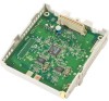
2.5 Installation of the Other Cards 2.5.4 EXT-CID Card Function Sends Caller ID signals to extension ports. Accessories and User-supplied Items Accessories (included): Extension Bolt × 1, Screw × 1 User-supplied (not included): none 64 Installation Manual - Panasonic KX-TAW84868 | Installation Manual - Page 65
Analog modem card for remote communication with the PBX. ITU-T V.90 support. RMT Card RMT Slot Accessories and User-supplied Items Accessories (included): none CAUTION Make sure to insert the RMT card between the guide rails until it locks into the RMT slot. Push the card firmly into - Panasonic KX-TAW84868 | Installation Manual - Page 66
2.5 Installation of the Other Cards Removing the RMT Card Pull open the guide rails using a flathead screwdriver and, while holding them open, remove the RMT card. 66 Installation Manual - Panasonic KX-TAW84868 | Installation Manual - Page 67
conditions. CS Hybrid Ports (Main Board) SLC8 Card PLC4, PLC8 Cards HLC4 Card APT DSS Console SLT " " indicates that the extension card or Hybrid Ports support the terminal. Installation Manual 67 - Panasonic KX-TAW84868 | Installation Manual - Page 68
"R". APT SLT Note In addition to an SLT, an answering machine, a fax machine or a modem (PC) can be connected in parallel with APTs. 68 Installation Manual - Panasonic KX-TAW84868 | Installation Manual - Page 69
through each CS. PS: 2.4 GHz Portable Station (KX-TD7680/KX-TD7690) The KX-TAW848 can support up to 28 PSs. For more details about the PS, refer to the PS Operating Instructions. CAUTION • The CS should be kept free of the site survey to determine the appropriate distance. Installation Manual 69 - Panasonic KX-TAW84868 | Installation Manual - Page 70
signal strength level is "12" near the CS. Using the KX-TD7680 19 0 Press 1, 9, and POWER for more than 2 seconds. Using the KX-TD7690 CS No. 1 to 9 Display example: > level is greater than "3" at any location within the service area demanded by the user. 70 Installation Manual - Panasonic KX-TAW84868 | Installation Manual - Page 71
a. Connect the CSs to the PBX. b. Register the PSs to the PBX. c. Walk around the service area while having a conversation using a registered PS. If noise is frequent or conversations disconnect, relocate the CSs Assuming everything goes as planned, mount the CS on the wall. Installation Manual 71 - Panasonic KX-TAW84868 | Installation Manual - Page 72
objects more than thick objects. • The table below shows the transmission tendency of radio waves when they reach objects made from various materials. 72 Installation Manual - Panasonic KX-TAW84868 | Installation Manual - Page 73
or diffracted. Steel Radio waves are usually reflected or diffracted, and rarely penetrate them. Wood Radio waves can penetrate them, but they are weakened. Installation Manual 73 - Panasonic KX-TAW84868 | Installation Manual - Page 74
ft]) Good conversation will be kept. C Out of Service: Cannot make/receive calls Radio Signal Strength Levels Level: the above information to the map. 2. Examine the service area demanded by the user on the map, one CS cannot cover the entire service area, install additional CSs as required - Panasonic KX-TAW84868 | Installation Manual - Page 75
. Therefore, you will need 4 CSs to cover the entire room. 100 m (328 ft) 70 m (230 ft) CS no. 1 CS no. 3 CS no. 2 CS no. 4 Installation Manual 75 - Panasonic KX-TAW84868 | Installation Manual - Page 76
must be set for each CS. If more than 1 CS is in Radio Signal Test mode, each CS must have a unique CS number. 76 Installation Manual - Panasonic KX-TAW84868 | Installation Manual - Page 77
outlet, as the weight of the adaptor may cause it to become disconnected. Modular Telephone Cord Power Supply Adaptor (PSZZ1TDA0142) To AC Adaptor (KX-A11/KX-TCA1)/ Battery Box (PSZZTD142CE) 4. Install the CS temporarily for the site survey. Install the CS at least 2 m (6 ft 7 in) above the floor - Panasonic KX-TAW84868 | Installation Manual - Page 78
Note The display language for the site survey is only in English. 1. Enter the Radio Signal Test mode. Using the KX-TD7680 19 0 Press 1, 9, and POWER for more than 2 seconds. To store the scan data Scan Data No. by a number; stored memory space will be indicated by a "-". 78 Installation Manual - Panasonic KX-TAW84868 | Installation Manual - Page 79
radio signal strength level is "8" by 5 to 10 meters (16 to 33 feet). CS no. 1 5 m to 10 m (16 ft to 33 ft) CS no. 2 Installation Manual 79 - Panasonic KX-TAW84868 | Installation Manual - Page 80
is greater than "3" at any location in the service area demanded by the user. Referring to the Stored Scan Data Using the KX-TD7680 19 Press 1, 9, and POWER for No.2 LEVEL: 9 When there is no scan data NO.0 NOT SAVED Using the KX-TD7690 19 Press 1, 9, and POWER for more than 2 seconds. 1 Scan - Panasonic KX-TAW84868 | Installation Manual - Page 81
19 Press 1, 9, and POWER for more than 2 seconds. 2 Scan Data No. 0 to 9, or # for all data To the Desired Scan Data No. Using the KX-TD7690 19 2 Press 1, 9, and POWER for more than 2 seconds. Scan Data No. 0 to 9, or # for all data To the Desired Scan Data No. 2.7 Connection of 2.4 - Panasonic KX-TAW84868 | Installation Manual - Page 82
or battery box from the CS and stop supplying electricity. 3. Switch all DIP switches on the CS from ON to OFF. OFF ON 1 2 3 4 5 6 82 Installation Manual - Panasonic KX-TAW84868 | Installation Manual - Page 83
Items for the CS Accessories (included): Screws × 2, Washers × 2 User-supplied (not included): RJ11 connector Note For details about HLC4 card, refer to "2.4.1 HLC4 Card". Installation Manual 83 - Panasonic KX-TAW84868 | Installation Manual - Page 84
through the groove of the CS (in any direction depending on your preference). TO MAIN UNIT / PABX To a Hybrid Port, or HLC4 card 84 Installation Manual - Panasonic KX-TAW84868 | Installation Manual - Page 85
both the PS and PBX is required. An APT with multiline display (e.g., KX-T7735) is required for the PBX system programming. Note For details about PT Programming" and "3.3 PT Programming" in the Feature Guide. Entering the System Programming Mode APT (Administrator Level) PROGRAM Manual 85 - Panasonic KX-TAW84868 | Installation Manual - Page 86
KX-TD7680 [ F2 ] Press POWER for 2 seconds. Press S2 repeatedly to select the desired language. Using the KX different PBXs. Using the KX-TD7680 Select "REGISTRATION". Using the KX-TD7690 SEL Select "REGISTRATION". for PS system setting. Using the KX-TD7680 Select "SYSTEM LOCK". Choose " - Panasonic KX-TAW84868 | Installation Manual - Page 87
Connection of 2.4 GHz Portable Stations Using the KX-TD7690 SEL CHNG Select "SYSTEM LOCK". SEL STORE 1 to 4 digits 1234 STORE END Setting the PIN for PS Using the KX-TD7680 Select "CHANGE PIN" Using the KX-TD7690 SEL Select "CHANGE PIN" S1 PIN for PS Registration 1 to 4 digits - Panasonic KX-TAW84868 | Installation Manual - Page 88
DELETE SYSTEM". Select the desired item. Select "YES". C.Tone Using the KX-TD7690 SEL SEL Select "DELETE SYSTEM". S1 Select the desired item. S1 Select "YES". SEL C.Tone S1 Testing the Operation Walk around the service area while having a conversation using a registered PS. If noise is - Panasonic KX-TAW84868 | Installation Manual - Page 89
screw heads are at the same distance from the wall. • Install the screws perpendicular to the wall. 3. Hook the CS on the screw heads. Installation Manual 89 - Panasonic KX-TAW84868 | Installation Manual - Page 90
of this page. If the dimension of the paper output still deviates slightly from the measurement indicated here, use the measurement indicated here. 90 Installation Manual - Panasonic KX-TAW84868 | Installation Manual - Page 91
External Sensors, and External Relays A maximum of 4 doorphones (KX-T30865), 4 door openers or external relays, and 4 external Sensor/ External Relay Device Installing the Doorphone (KX-T30865) 1. Loosen the screw to separate the doorphone into 2 halves. Panasonic Screw Installation Manual 91 - Panasonic KX-TAW84868 | Installation Manual - Page 92
the base cover to a wall using 2 screws. Screw To terminal box Note Two kinds of screws are included with KX-T30865. Please choose the appropriate kind for your wall type. : when a doorphone plate has been fixed to the box 4. Re-attach the 2 halves and re-insert the screw. 92 Installation Manual - Panasonic KX-TAW84868 | Installation Manual - Page 93
doorphones 2 and 4 to the yellow and black screws on the terminal box. To DPH4 card Yellow Red Panasonic Doorphone 3 Telephone Line Cord Terminal Box Black Green Panasonic Doorphone 4 Telephone Line Cord Yellow Red Panasonic Doorphone 1 Black Green Panasonic Doorphone 2 Installation Manual 93 - Panasonic KX-TAW84868 | Installation Manual - Page 94
Device 2. Attach the terminal blocks to the connectors of the DPH4 card in the PBX. To door openers/ external relays To external sensors 94 Installation Manual - Panasonic KX-TAW84868 | Installation Manual - Page 95
PBX and external music sources are not connected to the same ground, hum noise may be induced into Background Music and Music on Hold. Installation Manual 95 - Panasonic KX-TAW84868 | Installation Manual - Page 96
and external system database storage (save/load) functions. When using special accessories such as cable, the user should use those specified in this installation manual to comply with the limits for a Class B digital device pursuant to the FCC Rules. Note Use an RS-232C cross cable for connection - Panasonic KX-TAW84868 | Installation Manual - Page 97
when circuit CS (CTS) is OFF. • Frame Ground (FG) Connects to the unit frame and the earth ground conductor of the AC power cord. Installation Manual 97 - Panasonic KX-TAW84868 | Installation Manual - Page 98
used for system programming, diagnostics and external system database storage (save/load) functions. Pin Assignments No. Signal Name 2 1 1 3 42 3 4 VBUS USB DUSB D+ GND 98 Installation Manual - Panasonic KX-TAW84868 | Installation Manual - Page 99
current connection to the Power Failure Connection. Refer to "2.4.1 Power Failure Transfer" in the Feature Guide for further information. Note If DC power is provided by backup batteries, the PBX will , the conversation established during power failure will be maintained. Installation Manual 99 - Panasonic KX-TAW84868 | Installation Manual - Page 100
and is easily accessible. 1. Set the System Initialize Switch to the "SYSTEM INITIALIZE" position. RUN Indicator ALARM Indicator Reset Button System Initialize Switch 100 Installation Manual - Panasonic KX-TAW84868 | Installation Manual - Page 101
turning on the PBX. For safety reasons, do not stretch, bend, or pinch the AC cord and the DC cable of the AC adaptor. Installation Manual 101 - Panasonic KX-TAW84868 | Installation Manual - Page 102
will stop flashing and be kept lit. All data will be cleared, and the PBX as well as all optional service cards will be initialized to the default values. Note Use the same types of AC adaptor and AC cord that the PBX. To unplug, follow the reverse steps to plug it in. 102 Installation Manual - Panasonic KX-TAW84868 | Installation Manual - Page 103
Section 3 Guide for the PC Programming Software This section explains the installation and structure of the PC Programming Software. Installation Manual 103 - Panasonic KX-TAW84868 | Installation Manual - Page 104
PBX. To program and administer the PBX by PC, you need to install the KX-TAW848 Maintenance Console onto the PC. This manual describes overview and installation of the KX-TAW848 Maintenance Console only. KX-TAW848 Maintenance Console*1 Menu Bar Program Menu *1 The contents and design of the software - Panasonic KX-TAW84868 | Installation Manual - Page 105
3.2 Connection 3.2.1 Connection Serial Interface Connection 3.2 Connection RS-232C Port To COM Port PC To USB Port PC USB Port Note For pin assignments and maximum cabling distance, refer to "2.9.1 Connection of Peripherals". Installation Manual 105 - Panasonic KX-TAW84868 | Installation Manual - Page 106
cable for connection between the PBX and external modem. An AT command (for initialization, enabling automatic answer, etc.) can only be programmed by KX-TAW848 Maintenance Console. "AT&F0Q0E0V1S0=1X0&D0" is stored as the default value. For more information about the AT command, refer to the - Panasonic KX-TAW84868 | Installation Manual - Page 107
be used in system passwords, refer to "3.1.3 Entering Characters" in the Feature Guide. 6. If a system password is forgotten, it can be found by of the system data into a PC, and checking the password using the KX-TAW848 Maintenance Console software. If you do not have a backup of the Manual 107 - Panasonic KX-TAW84868 | Installation Manual - Page 108
the KX-TAW848 the KX-TDA USB driver, which is copied to the local drive during installation. 1. Copy the KX-TAW848 on-screen instructions provided by the installation wizard. Starting the KX-TAW848 Maintenance Console and the KX-TAW848 KX-TAW848 Maintenance Console" from the Start menu. 108 Installation - Panasonic KX-TAW84868 | Installation Manual - Page 109
levels, and the Quick Setup is only available when you start the KX-TAW848 Maintenance Console with the Installer Level Programmer Code. Note There are installer (default: 1234), then click [OK] to log-in. 6. Follow the instructions of the wizard and assign the basic items (Quick Setup). Installation - Panasonic KX-TAW84868 | Installation Manual - Page 110
• The PC will not perform any shutdown operation, or enter the power-saving system standby mode while the KX-TAW848 Maintenance Console is connected to the PBX. To perform either of the operations above, first close the connection to start when you try to restart the system. 110 Installation Manual - Panasonic KX-TAW84868 | Installation Manual - Page 111
Section 4 Troubleshooting This section provides information on the PBX and telephone troubleshooting. Installation Manual 111 - Panasonic KX-TAW84868 | Installation Manual - Page 112
4.1 Troubleshooting 4.1 Troubleshooting 4.1.1 Installation PROBLEM Extension does not operate. PROBABLE CAUSE Bad extension card. • Bad connection between ". See the error log using the KX-TAW848 Maintenance Console (refer to "4.1.5 Troubleshooting by Error Log"). 112 Installation Manual - Panasonic KX-TAW84868 | Installation Manual - Page 113
4.1 Troubleshooting 4.1.2 Connection Can you dial an extension? Connection between the PBX and an APT: CAUSE SOLUTION No The T/R is connected to the "R". D1 T R D2 PBX T R Extension SOLUTION Reverse the connections of the T/R. (Continued on the next page.) Installation Manual 113 - Panasonic KX-TAW84868 | Installation Manual - Page 114
4.1 Troubleshooting (Continued from the previous page.) Can you dial No out on a CO line? Connection between the central office and the PBX: CAUSE CO line is /R2 of the telephone jack using 2-conductor wiring. CO line is connected to the T2/R1. CO line T2 R1 T1 R2 PBX 114 Installation Manual - Panasonic KX-TAW84868 | Installation Manual - Page 115
4.1 Troubleshooting PROBLEM PROBABLE Flexible Buttons" in the Feature cannot be performed. APT. Guide. • Cannot register the PS. • Wrong Personal • Register PS. area. • PS stays out of service when the CS status is changed from Out of Service to In Service. • It may take about 10 s - Panasonic KX-TAW84868 | Installation Manual - Page 116
Troubleshooting 4.1.4 Using the Reset Button If the PBX does not operate properly, use the Reset Button. Before using the Reset Button, try the system feature again to confirm whether there definitely is a problem ALARM Indicator Reset Button System Initialize Switch 116 Installation Manual - Panasonic KX-TAW84868 | Installation Manual - Page 117
Troubleshooting by Error Log When a major system error occurs in the PBX, the ALARM indicator on the front of the cabinet turns on red, and the system logs the error information. Error Log Display Format Below is the display format of the error log. To see the error log using the KX Manual 117 - Panasonic KX-TAW84868 | Installation Manual - Page 118
Troubleshooting Item 5 Sub Code 6 Error Message Description Five-digit sub code (1XXYY) 1: Cabinet number XX: Slot number (00 to 06, 08 to 11) 00: MPR; 01: Hybrid Ports; 02 to 06, 08 to 11: Slots for optional service cards YY: Physical port number (01 to 16) For optional service Installation Manual - Panasonic KX-TAW84868 | Installation Manual - Page 119
recovered, the ALARM indicator will turn off automatically, indicating successful troubleshooting. When other errors are logged, the ALARM indicator will turn errors is cleared from the KXTAW848 Maintenance Console Optional Service Card Initial Self Diagnosis Error Code Error Message 212 Manual 119 - Panasonic KX-TAW84868 | Installation Manual - Page 120
Troubleshooting Detection of over current (short circuit on optional service cards) • Check the power supply system • • Replace the PBX • Remove the optional service cards and restart the PBX Battery out Main upload system files from the KX-TAW848 Note Maintenance Console Do not delete - Panasonic KX-TAW84868 | Installation Manual - Page 121
4.1 Troubleshooting Error Code Error Message 023 System data file • version error 024 of SD • Memory Card • SD Memory Card malfunction Main Board malfunction Too many optional service • cards installed Too many APTs connected • SOLUTION Restore the backup files Re-install the software - Panasonic KX-TAW84868 | Installation Manual - Page 122
4.1 Troubleshooting Error Code Error Message 092* CS connection service card Check the connection between the CS and PBX Check the Voice Processing System Check if the proper card is selected as the new clock master card Check the RS-232C cable Check the terminal equipment 122 Installation Manual - Panasonic KX-TAW84868 | Installation Manual - Page 123
Section 5 Appendix Installation Manual 123 - Panasonic KX-TAW84868 | Installation Manual - Page 124
5.1 Revision History 5.1 Revision History 5.1.1 MPR Version 2.0 Changed Contents • 2.8.1 Connection of Doorphones, Door Openers, External Sensors, and External Relays 124 Installation Manual - Panasonic KX-TAW84868 | Installation Manual - Page 125
Index Installation Manual 125 - Panasonic KX-TAW84868 | Installation Manual - Page 126
Console 108 Installing/Removing the Optional Service Cards 35 K KX-TAW84861 (4-Port Doorphone Card) 20, 59 KX-TAW84866 (8-Channel Echo Canceller Card) 20, 62 KX-TAW84868 (Extension Caller ID Card) 20, 64 KX-TAW84870 (4-Port Hybrid Extension Card) 20, 55 KX-TAW84874 (8-Port Single Line Telephone - Panasonic KX-TAW84868 | Installation Manual - Page 127
the KX-TAW848 Maintenance Console and Assigning the Basic Items (Quick Setup) 108 Starting the PBX 100 Surge Protector Installation 50 System Capacity 24 System Components Table 2 System Connection Diagram 18 System Highlights 16 System Outline 15 T The Structure of this Manual 9 Troubleshooting 111 - Panasonic KX-TAW84868 | Installation Manual - Page 128
Puerto Rico, lnc. Ave. 65 de Infantería, Km. 9.5 San Gabriel Industrial Park Carolina, Puerto Rico 00985 http://www.panasonic.com/csd Copyright: This material is copyrighted by Panasonic Communications Co., Ltd., and may be reproduced for internal use only. All other reproduction, in whole or in
-
 1
1 -
 2
2 -
 3
3 -
 4
4 -
 5
5 -
 6
6 -
 7
7 -
8
-
9
-
10
-
11
-
12
-
13
-
14
-
15
-
16
-
17
-
18
-
19
-
20
-
21
-
22
-
23
-
24
-
25
-
26
-
27
-
28
-
29
-
30
-
31
-
32
-
33
-
34
-
35
-
36
-
37
-
38
-
39
-
40
-
41
-
42
-
43
-
44
-
45
-
46
-
47
-
48
-
49
-
50
-
51
-
52
-
53
-
54
-
55
-
56
-
57
-
58
-
59
-
60
-
61
-
62
-
63
-
64
-
65
-
66
-
67
-
68
-
69
-
70
-
71
-
72
-
73
-
74
-
75
-
76
-
77
-
78
-
79
-
80
-
81
-
82
-
83
-
84
-
85
-
86
-
87
-
88
-
89
-
90
-
91
-
92
-
93
-
94
-
95
-
96
-
97
-
98
-
99
-
100
-
101
-
102
-
103
-
104
-
105
-
106
-
107
-
108
-
109
-
110
-
111
-
112
-
113
-
114
-
115
-
116
-
117
-
118
-
119
-
120
-
121
-
122
-
123
-
124
-
125
-
126
-
127
-
128
 |
 |

Advanced Hybrid & Wireless PBX
Installation Manual
Model No.
KX-TAW848
Thank you for purchasing a Panasonic Advanced Hybrid & Wireless PBX.
Please read this manual carefully before using this product and save this manual for future use.
KX-TAW848: MPR Version 2.0
SD Logo is
a trademark.