Panasonic KX-TG9341T Service Manual
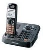
Panasonic KX-TG9341T - Cordless Phone - Metallic Manual
 |
UPC - 037988479504
View all Panasonic KX-TG9341T manuals
Add to My Manuals
Save this manual to your list of manuals |
Panasonic KX-TG9341T manual content summary:
- Panasonic KX-TG9341T | Service Manual - Page 1
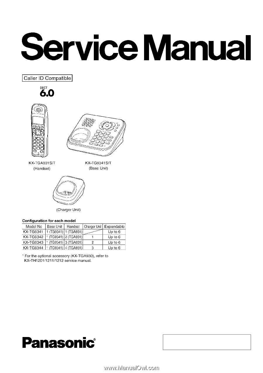
ORDER NO. KM40801513CE F13 Telephone Equipment Model No. KX-TG9341T KX-TG9342T KX-TG9343S KX-TG9343T KX-TG9344T KX-TGA931S KX-TGA931T Expandable Digital Cordless Answering System Pearl Silver Version Titanium Black Version (for U.S.A.) © 2008 Panasonic Communications Co., Ltd. All rights reserved. - Panasonic KX-TG9341T | Service Manual - Page 2
KX-TG9341T/KX-TG9342T/KX-TG9343S/KX-TG9343T/KX-TG9344T/KX-TGA931S/KX-TGA931T 2 - Panasonic KX-TG9341T | Service Manual - Page 3
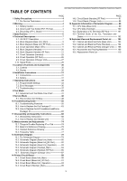
Terminal Guide of the ICs, Transistors and Diodes 102 16 Exploded View and Replacement Parts List --------- 103 16.1. Cabinet and Electrical Parts (Base Unit) --------- 103 16.2. Cabinet and Electrical Parts (Handset 104 16.3. Cabinet and Electrical Parts (Charger Unit) ----- 105 16.4. Accessories - Panasonic KX-TG9341T | Service Manual - Page 4
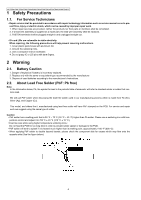
KX-TG9341T/KX-TG9342T/KX-TG9343S/KX-TG9343T/KX-TG9344T/KX-TGA931S/KX-TGA931T 1 Safety Precautions 1.1. For Service Technicians • Repair service shall be provided in accordance with repair technology information such as service manual so as to prevent fires, injury or electric shock, which can be - Panasonic KX-TG9341T | Service Manual - Page 5
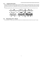
for using their product with other materials. The following lead free (PbF) solder wire sizes are recommended for service of this product: 0.3 mm, 0.6 mm and 1.0 mm. 2.3. Discarding of P. C. Board When discarding P. C. Board, delete all personal information such as telephone directory and caller - Panasonic KX-TG9341T | Service Manual - Page 6
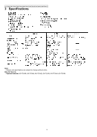
KX-TG9341T/KX-TG9342T/KX-TG9343S/KX-TG9343T/KX-TG9344T/KX-TGA931S/KX-TGA931T 3 Specifications Note: • Design and specifications are subject to change without notice. Note for Service: • Optional headset: KX-TCA60, KX-TCA86, KX-TCA92, KX-TCA93, KX-TCA94, KX-TCA95 6 - Panasonic KX-TG9341T | Service Manual - Page 7
4 Technical Descriptions KX-TG9341T/KX-TG9342T/KX-TG9343S/KX-TG9343T/KX-TG9344T/KX-TGA931S/KX-TGA931T 4.1. US-DECT Description The frequency range of 1.92 GHz-1.93 GHz is used. Transmitting and receiving carrier between base unit and handset is same frequency. Refer to Frequency Table (P.77). - Panasonic KX-TG9341T | Service Manual - Page 8
KX-TG9341T/KX-TG9342T/KX-TG9343S/KX-TG9343T/KX-TG9344T/KX-TGA931S/KX-TGA931T 4.1.3. Signal Flowchart in the Radio Parts Reception A voice signal from TEL line is encoded to digital data "TXDATA" by DSP (IC501) in a base unit. Then TXDATA goes to RF PART, and it's modulated to 1.9 GHz. The RF signal - Panasonic KX-TG9341T | Service Manual - Page 9
4.2. KX-TG9341T/KX-TG9342T/KX-TG9343S/KX-TG9343T/KX-TG9344T/KX-TGA931S/KX-TGA931T Block Diagram (Base Unit_Main) ANT1 ANT2 Operational P.C. Board KEYS X501 13.824 MHz SP RF_PART SYN_OUT SYN_EN SYN_CLK SYN_DATA SLOT_CTROL RADIO_EN TXDATA RXDATA IC501 DSP V_RF(VPA) V_RF - Panasonic KX-TG9341T | Service Manual - Page 10
KX-TG9341T/KX-TG9342T/KX-TG9343S/KX-TG9343T/KX-TG9344T/KX-TGA931S/KX-TGA931T 4.3. Block Diagram (Base Unit_RF Part) 10 ANT1 (*1) ANT2 (*1) D781 D771 Note: (*1) Antenna Type: wired dipole antenna IC741 3.0 V Regulator 4.0 V V_PA V_RF Divider 1.5 PLL delta-sigma Modulator DSP IC501 13.824 - Panasonic KX-TG9341T | Service Manual - Page 11
of voice signal. • Block Interface Circuit RF part, LED, Key scan, Speaker, Microphone, Telephone line. 4.4.2. Flash Memory (IC601) Following information data is stored. • Voice signal ex: Pre-recorded Greeting message, Incoming message • Settings ex: message numbers, ID code, Flash Time, Tone - Panasonic KX-TG9341T | Service Manual - Page 12
KX-TG9341T/KX-TG9342T/KX-TG9343S/KX-TG9343T/KX-TG9344T/KX-TGA931S/KX-TGA931T 4.4.3. Power Supply Circuit Function: The power supply voltage from AC adaptor is converted to the desired voltage of each block. Circuit Operation: • Q300 and IC300: 4.0 V DCDC Converter • IC331: 3.3 V Regulator 12 - Panasonic KX-TG9341T | Service Manual - Page 13
KX-TG9341T/KX-TG9342T/KX-TG9343S/KX-TG9343T/KX-TG9344T/KX-TGA931S/KX-TGA931T 4.4.3.1. Charge Circuit The voltage from the AC adaptor is supplied to the charge circuits. 13 - Panasonic KX-TG9341T | Service Manual - Page 14
KX-TG9341T/KX-TG9342T/KX-TG9343S/KX-TG9343T/KX-TG9344T/KX-TGA931S/KX-TGA931T 4.4.4. Reset Circuit Function: This circuit is used to initialize the microcomputer when it incorporates an AC adaptor. Circuit Operation: When the AC Adaptor is inserted into the unit, then the voltage is shifted by IC331 - Panasonic KX-TG9341T | Service Manual - Page 15
KX-TG9341T/KX-TG9342T/KX-TG9343S/KX-TG9343T/KX-TG9344T/KX-TGA931S/KX-TGA931T 4.4.5. Telephone Line Interface Telephone Line Interface Circuit: connected as to cut the DC loop current and to cut the voice signal. The unit is consequently in an onhook condition. Pulse Dial Circuit: Pin 59 of DSP turns - Panasonic KX-TG9341T | Service Manual - Page 16
KX-TG9341T/KX-TG9342T/KX-TG9343S/KX-TG9343T/KX-TG9344T/KX-TGA931S/KX-TGA931T 4.4.6. Auto Disconnect Circuit Function: This circuit is used to detect the fact that another telephone connected to the same line is OFF-HOOK while the unit is in a receiving status or OGM transmitting status. Circuit - Panasonic KX-TG9341T | Service Manual - Page 17
KX-TG9341T/KX-TG9342T/KX-TG9343S/KX-TG9343T/KX-TG9344T/KX-TGA931S/KX-TGA931T 4.4.7. Parallel Connection Detect Circuit Function: In order to disable call waiting and stutter tone functions when using telephones connected in parallel, it is necessary to have a circuit that judges whether a telephone - Panasonic KX-TG9341T | Service Manual - Page 18
KX-TG9341T/KX-TG9342T/KX-TG9343S/KX-TG9343T/KX-TG9344T/KX-TGA931S/KX-TGA931T 4.4.8. Calling Line Identification (Caller ID)/Call Waiting Caller ID Function: Caller ID The caller ID is a chargeable ID which the user of a telephone circuit obtains by entering a contract with the telephone company to - Panasonic KX-TG9341T | Service Manual - Page 19
KX-TG9341T/KX-TG9342T/KX-TG9343S/KX-TG9343T/KX-TG9344T/KX-TGA931S/KX-TGA931T Call Waiting Caller ID Calling Identity Delivery on Call Waiting (CIDCW) is a CLASS service that allows a customer, while off-hook on an existing call, to receive information about a calling party on a waited call. The - Panasonic KX-TG9341T | Service Manual - Page 20
KX-TG9341T/KX-TG9342T/KX-TG9343S/KX-TG9343T/KX-TG9344T/KX-TGA931S/KX-TGA931T 4.5. Block Diagram (Handset) IC541 EEPROM X501 13.824 MHz Q531 CHARGE DETECT Q362, Q364 CHARGE CONTROL CHARGE Q361 BATTERY RST D361 IC374 RST IC371 2.7 V REGULATOR MIC IC561 DC/DC CONVERTER LCD BACK LIGHT LED551- - Panasonic KX-TG9341T | Service Manual - Page 21
4.6. KX-TG9341T/KX-TG9342T/KX-TG9343S/KX-TG9343T/KX-TG9344T/KX-TGA931S/KX-TGA931T Block Diagram (Handset_RF Part) IC741 2.7 V Regulator 3.1 V V_PA V_RF 21 ANT1 difference between base unit and handset in Radio parts) ANT1: wired dipole antenna ANT2: patterned antenna KX-TGA931 BLOCK DIAGRAM ( - Panasonic KX-TG9341T | Service Manual - Page 22
KX-TG9341T/KX-TG9342T/KX-TG9343S/KX-TG9343T/KX-TG9344T/KX-TGA931S/KX-TGA931T 4.7. Circuit Operation (Handset) 4.7.1. Construction The circuit mainly consists of DSP and RF part as shown in the block diagram. 4.7.1.1. DSP: IC501 Function • Battery Low, Power down detect circuit • Ringer Generation • - Panasonic KX-TG9341T | Service Manual - Page 23
4.7.2. Power Supply Circuit Voltage is supplied separately to each block. KX-TG9341T/KX-TG9342T/KX-TG9343S/KX-TG9343T/KX-TG9344T/KX-TGA931S/KX-TGA931T 23 - Panasonic KX-TG9341T | Service Manual - Page 24
KX-TG9341T/KX-TG9342T/KX-TG9343S/KX-TG9343T/KX-TG9344T/KX-TGA931S/KX-TGA931T 4.7.3. Charge Circuit When the handset is put on the cradle of the base unit, the power is supplied from CHARGE+ and CHARGE- terminals to charge the battery via R366 or Q361. The voltage between CHARGE+ and CHARGE- flows - Panasonic KX-TG9341T | Service Manual - Page 25
KX-TG9341T/KX-TG9342T/KX-TG9343S/KX-TG9343T/KX-TG9344T/KX-TGA931S/KX-TGA931T 4.7.5. Sending Signal The voice signal from the microphone is input to DSP (90, 91). CN431 is the headset jack. When the headphone is connected, the R436/R437 detects it. The input from the microphone of the handset (MIM, - Panasonic KX-TG9341T | Service Manual - Page 26
below, the various voltages are supplied to each block. V_PA, about 3.2 V at base unit or 3.1 V at handset, is supplied to the Power amplifier. IC741 is 3.0 V at base unit or 2.7 V at handset Regulator and outputs VRF (3.0 V at base unit or 2.7 V at handset) by order of RADIO_EN signal. V_RF is - Panasonic KX-TG9341T | Service Manual - Page 27
KX-TG9341T/KX-TG9342T/KX-TG9343S/KX-TG9343T/KX-TG9344T/KX-TGA931S/KX-TGA931T Circuit Operation (Charger Unit) The voltage from the AC adaptor is supplied to the charge circuits. Main charge (180~250 mA at the Battery) of maximum 7hours is started soon after the handset is placed on the charger unit - Panasonic KX-TG9341T | Service Manual - Page 28
KX-TG9341T/KX-TG9342T/KX-TG9343S/KX-TG9343T/KX-TG9344T/KX-TGA931S/KX-TGA931T 4.10. Signal Route 28 - Panasonic KX-TG9341T | Service Manual - Page 29
RF part signal route KX-TG9341T/KX-TG9342T/KX-TG9343S/KX-TG9343T/KX-TG9344T/KX-TGA931S/KX-TGA931T 29 - Panasonic KX-TG9341T | Service Manual - Page 30
KX-TG9341T/KX-TG9342T/KX-TG9343S/KX-TG9343T/KX-TG9344T/KX-TGA931S/KX-TGA931T 5 Location of Controls and 5.1.2. Components 5.1. Controls 5.1.1. Base Unit Handset 5.2. Display 30 - Panasonic KX-TG9341T | Service Manual - Page 31
6 Installation Instructions 6.1. Connections KX-TG9341T/KX-TG9342T/KX-TG9343S/KX-TG9343T/KX-TG9344T/KX-TGA931S/KX-TGA931T 6.2. Battery 6.2.1. Battery Installation and Replacement 31 - Panasonic KX-TG9341T | Service Manual - Page 32
KX-TG9341T/KX-TG9342T/KX-TG9343S/KX-TG9343T/KX-TG9344T/KX-TGA931S/KX-TGA931T 6.2.2. Battery Charge 6.2.4. Panasonic Ni-MH Battery Performance (supplied batteries) Note for service: The battery strength may not be indicated correctly if the battery is disconnected and connected again, even after - Panasonic KX-TG9341T | Service Manual - Page 33
7 Operating Instructions 7.1. Programmable Settings KX-TG9341T/KX-TG9342T/KX-TG9343S/KX-TG9343T/KX-TG9344T/KX-TGA931S/KX-TGA931T 7.1.1. Programming by Scrolling through the Display Menus 33 - Panasonic KX-TG9341T | Service Manual - Page 34
KX-TG9341T/KX-TG9342T/KX-TG9343S/KX-TG9343T/KX-TG9344T/KX-TGA931S/KX-TGA931T 7.1.2. Programming using the Direct Commands 34 - Panasonic KX-TG9341T | Service Manual - Page 35
KX-TG9341T/KX-TG9342T/KX-TG9343S/KX-TG9343T/KX-TG9344T/KX-TGA931S/KX-TGA931T 35 - Panasonic KX-TG9341T | Service Manual - Page 36
KX-TG9341T/KX-TG9342T/KX-TG9343S/KX-TG9343T/KX-TG9344T/KX-TGA931S/KX-TGA931T 7.2. Error Messages 36 - Panasonic KX-TG9341T | Service Manual - Page 37
7.3. Troubleshooting KX-TG9341T/KX-TG9342T/KX-TG9343S/KX-TG9343T/KX-TG9344T/KX-TGA931S/KX-TGA931T 37 - Panasonic KX-TG9341T | Service Manual - Page 38
KX-TG9341T/KX-TG9342T/KX-TG9343S/KX-TG9343T/KX-TG9344T/KX-TGA931S/KX-TGA931T 38 - Panasonic KX-TG9341T | Service Manual - Page 39
KX-TG9341T/KX-TG9342T/KX-TG9343S/KX-TG9343T/KX-TG9344T/KX-TGA931S/KX-TGA931T 39 - Panasonic KX-TG9341T | Service Manual - Page 40
KX-TG9341T/KX-TG9342T/KX-TG9343S/KX-TG9343T/KX-TG9344T/KX-TGA931S/KX-TGA931T 40 - Panasonic KX-TG9341T | Service Manual - Page 41
8 Test Mode KX-TG9341T/KX-TG9342T/KX-TG9343S/KX-TG9343T/KX-TG9344T/KX-TGA931S/KX-TGA931T 8.1. Adjustment and Test Mode Flow Chart 8.1.1. TX-CW Mode for Base Unit Note: (*1) Refer to Check Table for RF part (P.58). 41 - Panasonic KX-TG9341T | Service Manual - Page 42
KX-TG9341T/KX-TG9342T/KX-TG9343S/KX-TG9343T/KX-TG9344T/KX-TGA931S/KX-TGA931T 8.1.2. Test Link Mode for Base Unit Note: (*1) Refer to Test Link Mode for Handset (P.46). If you can not proceed to the next step, refer to Registering a Handset to a Base Unit (P.56). (*2) Refer to Check Table for RF part - Panasonic KX-TG9341T | Service Manual - Page 43
8.1.3. Adjustment Mode for Base Unit KX-TG9341T/KX-TG9342T/KX-TG9343S/KX-TG9343T/KX-TG9344T/KX-TGA931S/KX-TGA931T Cross Reference Check and Adjust Frequency (Base Unit) (P.74) 43 - Panasonic KX-TG9341T | Service Manual - Page 44
KX-TG9341T/KX-TG9342T/KX-TG9343S/KX-TG9343T/KX-TG9344T/KX-TGA931S/KX-TGA931T 8.1.4. TX-CW Mode for Handset Note: (*1) LCD displays the Channel number. (exception: default/ CH00 = 0ch.) (*2) Refer to Check Table for RF part (P.58). 44 - Panasonic KX-TG9341T | Service Manual - Page 45
8.1.5. RX-CW Test Mode for Handset KX-TG9341T/KX-TG9342T/KX-TG9343S/KX-TG9343T/KX-TG9344T/KX-TGA931S/KX-TGA931T Note: (*1) LCD displays the Channel number. (exception: default/ CH00 = 0ch.) (*2) Refer to Check Table for RF part (P.58). 45 - Panasonic KX-TG9341T | Service Manual - Page 46
/KX-TGA931S/KX-TGA931T 8.1.6. Test Link Mode for Handset Note: (*1) LCD displays the Channel number. (exception: default/ CH00 = 0ch.) (*2) If can not proceed to the next step, refer to Registering a Handset to a Base Unit (P.56). (*3) for factory use only. (*4) Refer to Check Table for RF part - Panasonic KX-TG9341T | Service Manual - Page 47
Adjustment Mode for Handset KX-TG9341T/KX-TG9342T/KX-TG9343S/KX-TG9343T/KX-TG9344T/KX-TGA931S/KX-TGA931T Cross Reference (*1) Adjust Battery Low Detector Voltage (Handset) (P.74) Note: (*2) These are the default values. (*3) These values may not be fixed depending on the battery strength. 47 - Panasonic KX-TG9341T | Service Manual - Page 48
/KX-TGA931T 9 Service Mode 9.1. How to Clear User Setting Units are reset to the Factory settings by this operation (Erase recorded Voice messages, stored Phone numbers, Caller list and etc.). This operation should not be performed for a usual repair. 9.1.1. Base Unit Note: (*1) Telephone line - Panasonic KX-TG9341T | Service Manual - Page 49
9.1.2. Handset KX-TG9341T/KX-TG9342T/KX-TG9343S/KX-TG9343T/KX-TG9344T/KX-TGA931S/KX-TGA931T Note: (*1) Be sure to short the battery terminals of the handset with a lead wire, etc. for 2 seconds for discharge after removing the battery. 49 - Panasonic KX-TG9341T | Service Manual - Page 50
Guide 10.1. Troubleshooting Flowchart Cross Reference: Check Power (P.51) Check Playback (P.53) Check Record (P.52) Check Battery Charge (P.53) Check Link (P.54) Check the RF part (P.55) Check Handset Transmission (P.62) Check Handset Reception (P.62) Check Caller ID (P.62) Note: (*1) When a user - Panasonic KX-TG9341T | Service Manual - Page 51
/KX-TG9342T/KX-TG9343S/KX-TG9343T/KX-TG9344T/KX-TGA931S/KX-TGA931T Cross Reference: Power Supply Circuit (P.12) Reset Circuit (P.14) Note: Flash Memory is IC601. DSP is IC501. (*1) Refer to Specifications (P.6) for part number and supply voltage of AC adaptor. (*2) Refer to Circuit Board (Base - Panasonic KX-TG9341T | Service Manual - Page 52
KX-TG9341T/KX-TG9342T/KX-TG9343S/KX-TG9343T/KX-TG9344T/KX-TGA931S/KX-TGA931T 10.1.2. Check Record BASE UNIT A) Not record Greeting Message B) Not record Incoming Message C) How to change the Auto Disconnect activation (time) Some Telephone Company lines (fiber or cable) ON Hook and OFF Hook - Panasonic KX-TG9341T | Service Manual - Page 53
10.1.3. Check Playback KX-TG9341T/KX-TG9342T/KX-TG9343S/KX-TG9343T/KX-TG9344T/KX-TGA931S/KX-TGA931T Cross Reference: Power Supply Circuit (P.12) 10.1.4. Check Battery Charge Note: Flash Memory is IC601. DSP is IC501. (*1) Refer to Circuit Board (Base Unit_Main) (P.89). Note: Flash Memory is - Panasonic KX-TG9341T | Service Manual - Page 54
KX-TG9341T/KX-TG9342T/KX-TG9343S/KX-TG9343T/KX-TG9344T/KX-TGA931S/KX-TGA931T 10.1.5. Check Link Note: Flash Memory is IC601. DSP is IC501. (*1) Refer to Finding out the Defective part (P.55). Cross Reference: Check the RF part (P.55) 54 - Panasonic KX-TG9341T | Service Manual - Page 55
RF part 10.1.6.1. Finding out the Defective part KX-TG9341T/KX-TG9342T/KX-TG9343S/KX-TG9343T/KX-TG9344T/KX-TGA931S/KX-TGA931T After All the Checkings or Repairing 1. Re-register the checked handset to the checked base unit, and Regular HS to Regular BU. Note: (*1) HS: Handset (*2) BU: Base Unit - Panasonic KX-TG9341T | Service Manual - Page 56
KX-TG9341T/KX-TG9342T/KX-TG9343S/KX-TG9343T/KX-TG9344T/KX-TGA931S/KX-TGA931T 10.1.6.1.1. Registering a Handset to a Base Unit 10.1.6.1.2. Deregistering a Handset 10.1.6.1.3. Deregistering All Handsets by the Base Unit 56 - Panasonic KX-TG9341T | Service Manual - Page 57
KX-TG9341T/KX-TG9342T/KX-TG9343S/KX-TG9343T/KX-TG9344T/KX-TGA931S/KX-TGA931T 10.1.6.2. RF Check Flowchart Each item (1 ~ 6) of RF Check Flowchart corresponds to Check Table for RF part (P.58). Please refer to the each item. Note: (*1) Refer to Things to Do after Replacing IC or X'tal (P.74). 57 - Panasonic KX-TG9341T | Service Manual - Page 58
KX-TG9341T/KX-TG9342T/KX-TG9343S/KX-TG9343T/KX-TG9344T/KX-TGA931S/KX-TGA931T 10.1.6.3. Check Table for RF part No. Item 1 Link (Base Unit) Check 1. Register Regular HS to BU (to be checked). 2. Press [Talk] key of the Regular HS to establish link. Check DSP interface. (*2) HS (Handset - Panasonic KX-TG9341T | Service Manual - Page 59
KX-TG9341T/KX-TG9342T/KX-TG9343S/KX-TG9343T/KX-TG9344T/KX-TGA931S/KX-TGA931T 10.1.6.4. TEST RANGE Check Circuit block which range is defective can be found by the following check. Item BU (Base Unit the BU and the Regular HS by CHART1. HS (Handset) Check 1. Register HS (to be checked) to Regular - Panasonic KX-TG9341T | Service Manual - Page 60
KX-TG9341T/KX-TG9342T/KX-TG9343S/KX-TG9343T/KX-TG9344T/KX-TGA931S/KX-TGA931T 10.1.6.5. RF-DSP Interface Signal Wave Form Control signal for Base Unit ( 24 22 19 23 30 24 29 25 28 Control signal for Handset (Active normal mode after power-on) RADEOEN SLOT_CTRL SYN_DATA SYN_CLK SYN_EN 400 - Panasonic KX-TG9341T | Service Manual - Page 61
KX-TG9341T/KX-TG9342T/KX-TG9343S/KX-TG9343T/KX-TG9344T/KX-TGA931S/KX-TGA931T Base Unit TR-DATA Signal (Normal mode) Base unit sends a dummy slot and receves all 6 slots every frame in normal mode. Pin Number (Base unit) ITEM MODE IC701 IC501 (BU) [HS] or [REG HS] TEST TX_CW RADIOEN 21 24 - Panasonic KX-TG9341T | Service Manual - Page 62
KX-TGA931T 10.1.7. Check Handset Transmission Cross Reference: Signal Route (P.28) 10.1.8. Check Handset Reception Cross Reference: Signal Route (P.28) Note: When checking the RF part, Refer to Check the RF part (P.55). 10.1.9. Check Caller ID Cross Reference: Telephone Line Interface (P.15) Calling - Panasonic KX-TG9341T | Service Manual - Page 63
KX-TG9341T/KX-TG9342T/KX-TG9343S/KX-TG9343T/KX-TG9344T/KX-TGA931S/KX-TGA931T 10.2. How to Replace the Flat Package IC 10.2.1. Preparation • PbF (: Pb free) Solder • Soldering Iron Tip Temperature of 700 °F ± 20 °F (370 °C ± 10 °C) Note: We recommend a 30 to 40 - Panasonic KX-TG9341T | Service Manual - Page 64
KX-TG9341T/KX-TG9342T/KX-TG9343S/KX-TG9343T/KX-TG9344T/KX-TGA931S/KX-TGA931T 10.2.3. How to Install the IC 1. Temporarily fix the FLAT PACKAGE IC, Bridge 1. Lightly resolder the bridged portion. 2. Remove the remaining solder along the pins using a soldering iron as shown in the figure below. 64 - Panasonic KX-TG9341T | Service Manual - Page 65
KX-TG9341T/KX-TG9342T/KX-TG9343S/KX-TG9343T/KX-TG9344T/KX-TGA931S/KX-TGA931T 10.3. How to Replace the LLP (Leadless Leadframe Package) IC 10.3.1. Preparation • PbF (: Pb along perforation. 2. Remove the cut part. 3. Cut the four corners along perforation. 4. Remove the reminds by melting solder. 65 - Panasonic KX-TG9341T | Service Manual - Page 66
KX-TG9341T/KX-TG9342T/KX-TG9343S/KX-TG9343T/KX-TG9344T/KX-TGA931S/KX-TGA931T 10.3.4. How to Install the Shield etc. when the solder is melted completely. Note: • Be careful not to touch the peripheral parts with tweezers, etc. They are unstable. When it is hard to melt the solder completely, heat - Panasonic KX-TG9341T | Service Manual - Page 67
KX-TG9341T/KX-TG9342T/KX-TG9343S/KX-TG9343T/KX-TG9344T/KX-TGA931S/KX-TGA931T 10.3.6. How to Install the IC 1. Place the solder a little on the land where the radiation GND pad on IC bottom is to be - Panasonic KX-TG9341T | Service Manual - Page 68
KX-TG9341T/KX-TG9342T/KX-TG9343S/KX-TG9343T/KX-TG9344T/KX-TGA931S/KX-TGA931T 11 Disassembly and Assembly Instructions 11.1. Disassembly Instructions 11.1.1. Base Unit 68 - Panasonic KX-TG9341T | Service Manual - Page 69
KX-TG9341T/KX-TG9342T/KX-TG9343S/KX-TG9343T/KX-TG9344T/KX-TGA931S/KX-TGA931T 69 - Panasonic KX-TG9341T | Service Manual - Page 70
KX-TG9341T/KX-TG9342T/KX-TG9343S/KX-TG9343T/KX-TG9344T/KX-TGA931S/KX-TGA931T 11.1.2. Handset 70 - Panasonic KX-TG9341T | Service Manual - Page 71
11.1.3. Charger Unit KX-TG9341T/KX-TG9342T/KX-TG9343S/KX-TG9343T/KX-TG9344T/KX-TGA931S/KX-TGA931T 71 - Panasonic KX-TG9341T | Service Manual - Page 72
KX-TG9341T/KX-TG9342T/KX-TG9343S/KX-TG9343T/KX-TG9344T/KX-TGA931S/KX-TGA931T 11.2. How to Replace the Handset LCD 72 - Panasonic KX-TG9341T | Service Manual - Page 73
KX-TG9341T/KX-TG9342T/KX-TG9343S/KX-TG9343T/KX-TG9344T/KX-TGA931S/KX-TGA931T 73 - Panasonic KX-TG9341T | Service Manual - Page 74
KX-TG9341T/KX-TG9342T/KX-TG9343S/KX-TG9343T/KX-TG9344T/KX-TGA931S/KX-TGA931T 12 Measurements and Adjustments 12.1. Things to Do after Replacing IC or X'tal 12.1.1. Preparation Equipment: Frequency counter Check Point for measurement: BCK Checking tolerance: 13.824 MHz ± 100 Hz (Base Unit)/13.824 MHz - Panasonic KX-TG9341T | Service Manual - Page 75
12.2. Base Unit Reference Drawing KX-TG9341T/KX-TG9342T/KX-TG9343S/KX-TG9343T/KX-TG9344T/KX-TGA931S/KX-TGA931T When connecting the simulator equipment for checking, please refer to below. DC 6.5 V Spectrum MIN MIP MIC AF OSC Note: (*1) is referred to No.3 of Check Table for RF part (P.58). 75 - Panasonic KX-TG9341T | Service Manual - Page 76
KX-TG9341T/KX-TG9342T/KX-TG9343S/KX-TG9343T/KX-TG9344T/KX-TGA931S/KX-TGA931T 12.3. Handset Reference Drawing When connecting the simulator equipment for checking, please refer to below. Note: (*1) is referred to No.3 of Check Table for RF part (P.58). 76 MIC Load OSC 1.1 kHz DC_POWER_SUPPLY 2.6 V - Panasonic KX-TG9341T | Service Manual - Page 77
12.4. Frequency Table KX-TG9341T/KX-TG9342T/KX-TG9343S/KX-TG9343T/KX-TG9344T/KX-TGA931S/KX-TGA931T Channel 0 Channel 1 Channel 2 Channel 3 Channel 4 Ch. (hex) 00 01 02 03 04 TX/RX Frequency (MHz) 1928.448 1926.720 1924.992 1923.264 1921.536 77 - Panasonic KX-TG9341T | Service Manual - Page 78
KX-TG9341T/KX-TG9342T/KX-TG9343S/KX-TG9343T/KX-TG9344T/KX-TGA931S/KX-TGA931T Memo 78 - Panasonic KX-TG9341T | Service Manual - Page 79
Diagram KX-TG9341T/KX-TG9342T/KX-TG9343S/KX-TG9343T/KX-TG9344T/KX-TGA931S/KX-TGA931T 13.1. For Schematic Diagram 13.1.1. Base Unit (Schematic Diagram (Base Unit_Main)) 13.1.1.1. Acoustic Testing Mode Notes: 1. DC voltage measurements are taken with voltmeter from the negative voltage line - Panasonic KX-TG9341T | Service Manual - Page 80
KX-TG9341T/KX-TG9342T/KX-TG9343S/KX-TG9343T/KX-TG9344T/KX-TGA931S/KX-TGA931T 13.2. Schematic Diagram (Base SDA For TH12 series 23 C605 NC C604 NC *IC601 1 SI 2 SCK 3 *RESET 4 *CS SO 8 GND 7 VCC 6 *WP 5 16M R602 NC R603 NC *R672 220 *R671 330 Power ON (Reset) C660 0.1u *R665 NC 2 1 - Panasonic KX-TG9341T | Service Manual - Page 81
NC *R363 NC CHARGE- L372 *L371 6.8uH NC R371 NC *R372 6.8 C301 NC REFERENCE 1XX : TEL LINE 3XX : POWER, CHARGE 4XX : RESET, MIC, SP 5XX : DSP, RF I/F 6XX : FLASH, KEY, LCD 7XX : RF(2.4G) 8XX E B C Bell detection A NC: No Components KX-TG9341/9342/9343/9344 SCHEMATIC DIAGRAM (Base Unit_Main) 81 - Panasonic KX-TG9341T | Service Manual - Page 82
KX-TG9341T/KX-TG9342T/KX-TG9343S/KX-TG9343T/KX-TG9344T/KX-TGA931S/KX-TGA931T 13.3. Schematic Diagram (Base Unit_RF Part) 82 ANT2 C793 D10p L791 3.9n C797 D10p ANT1 L795 3.9n .01 RF_RSTN 3.2V FP:3.2V V_PA PP:3.1V NC: No Components KX-TG9341/9342/9343/9344 SCHEMATIC DIAGRAM (Base Unit_RF Part) - Panasonic KX-TG9341T | Service Manual - Page 83
KX-TG9341T/KX-TG9342T/KX-TG9343S/KX-TG9343T/KX-TG9344T/KX-TGA931S/KX-TGA931T 13.4. Schematic Diagram (Base Unit_Operation) ANS MSG VCC 2APVCC MEG_LED ANS_LED KEYS_B KEYIN1 KEYIN2 KEYIN3 KEYS_C KEYS_D KEYS_E LED902 LED901 K A KA MEMO 2 1 ERASE 1 2 RPT 1 2 STOP 2 1 REC 2 1 CHK 2 1 - Panasonic KX-TG9341T | Service Manual - Page 84
KX-TG9341T/KX-TG9342T/KX-TG9343S/KX-TG9343T/KX-TG9344T/KX-TGA931S/KX SYN_OUT RF control line Flash memory for booting 1 SI SO 8 2 SCK GND 7 3 *RESET VCC 6 4 *Q562 *Q563 NC Q561 C573 K0.1 C504 K0.1 C511 NC DSP Part (control circuit) (1) (2) RST R525 NC (3) X501 13.824MHz R501 1M - Panasonic KX-TG9341T | Service Manual - Page 85
C379 K0.1 R379 2.2M R378 1.0M C544 K0.1 C543 NC KX-TG9341T/KX-TG9342T/KX-TG9343S/KX-TG9343T/KX-TG9344T/KX-TGA931S/KX-TGA931T C509 NC C243 NC *R431 NC C508 6.3V 10uF R508 -1 MIC-TP 2 1 MIC MIC-TP MICP MICP-1 Handset TX 88mVp-p/600 IN SP phone TX 30mVp-p/600 IN C371 K1.0 R543 270k C373 330u - Panasonic KX-TG9341T | Service Manual - Page 86
KX-TG9341T/KX-TG9342T/KX-TG9343S/KX-TG9343T/KX-TG9344T/KX-TGA931S/KX-TGA931T 13.6. Schematic Diagram (Handset_RF Part) 86 ANT2 C793 B3.3p L791 5.6n ANT1 C797 B3.3p L795 5.6n C738 D10p C737 K0.01 RF_RSTN 3.1V PP:3.1V V_PA NC: No Components KX-TGA931 SCHEMATIC DIAGRAM (Handset_RF Part) - Panasonic KX-TG9341T | Service Manual - Page 87
13.7. KX-TG9341T/KX-TG9342T/KX-TG9343S/KX-TG9343T/KX-TG9344T/KX-TGA931S/KX-TGA931T Schematic Diagram (Charger Unit) TP3 1 F1 2 J1 AK D1 R1 10 TP2 TP4 TP1 G SCHEMATIC DIAGRAM (Charger Unit) 87 - Panasonic KX-TG9341T | Service Manual - Page 88
KX-TG9341T/KX-TG9342T/KX-TG9343S/KX-TG9343T/KX-TG9344T/KX-TGA931S/KX-TGA931T Memo 88 - Panasonic KX-TG9341T | Service Manual - Page 89
14 Printed Circuit Board KX-TG9341T/KX-TG9342T/KX-TG9343S/KX-TG9343T/KX-TG9344T/KX-TGA931S/KX-TGA931T P101 SA102 C101 SA101 14.1. Circuit Board (Base Unit_Main) 14.1.1. Component View DC ANT1_HOT2 ANT1 C301 C306 3.0A F301 D301 C305 3 Q300 4 R308 IC300 1 R303 R304 5 C304 C308 L300 C102 - Panasonic KX-TG9341T | Service Manual - Page 90
KX-TG9341T/KX-TG9342T/KX-TG9343S/KX-TG9343T/KX-TG9344T/KX-TGA931S/KX-TGA931T 14.1.2. Bottom View Vcc Digital Vcc 13.824 MHz BCLK ANT2_HOT ANT2_GND for TH12xx Series MICMIC+ MIC1 A PNLP1004/1005/1009/1010/1011/1012 INT1 KX-TG9341/9342/9343/9344 CIRCUIT BOARD (Base Unit_Main (Bottom View)) 90 - Panasonic KX-TG9341T | Service Manual - Page 91
KX-TG9341T/KX-TG9342T/KX-TG9343S/KX-TG9343T/KX-TG9344T/KX-TGA931S/KX-TGA931T 14.2. Circuit Board (Base Unit_RF Part) C797 L795 C793 C792 IC741 C795 L791 R772 C775 C781 C796 C776 C777 R781 C773 R771 D771 C762 R761 C765 C763 R763 R762 C771 C764 - Panasonic KX-TG9341T | Service Manual - Page 92
KX-TG9341T/KX-TG9342T/KX-TG9343S/KX-TG9343T/KX-TG9344T/KX-TGA931S/KX-TGA931T Memo 92 - Panasonic KX-TG9341T | Service Manual - Page 93
KX-TG9341T/KX-TG9342T/KX-TG9343S/KX-TG9343T/KX-TG9344T/KX-TGA931S/KX-TGA931T 14.3. Circuit Board (Base Unit_Operation) 14.3.1. Component View PbF KX-TG9341H PQUP11555Z PNLP1014Z WBX01 WBX02 10 6 A 1 1 KX-TG9341/9342/9343/9344 CIRCUIT BOARD (Base Unit_Operation (Component View)) 93 - Panasonic KX-TG9341T | Service Manual - Page 94
KX-TG9341T/KX-TG9342T/KX-TG9343S/KX-TG9343T/KX-TG9344T/KX-TGA931S/KX-TGA931T 14.3.2. Bottom View PbF KX-TG9341H UP ERASE LED901 ANS2 MEMO STOP RPT MSG1 MSG2 SKIP LED902 DOWN LOCAT/INT SP2 SP LED904 VCC ANS A KX-TG9341/9342/9343/9344 CIRCUIT BOARD (Base Unit_Operation (Bottom View)) 94 - Panasonic KX-TG9341T | Service Manual - Page 95
14.4. Circuit Board (Handset_Main) 14.4.1. Component View KX-TG9341T/KX-TG9342T/KX-TG9343S/KX-TG9343T/KX-TG9344T/KX-TGA931S/KX-TGA931T ANT1_HOT4 ANT1 KX-TGA93 R ANT1_HOT3 PQUP11558Z PbF C795 L791 R772 C775 C781 C796 C776 C777 R781 C797 L795 C793 C762 R761 C765 C763 R763 R762 C771 C764 - Panasonic KX-TG9341T | Service Manual - Page 96
KX-TG9341T/KX-TG9342T/KX-TG9343S/KX-TG9343T/KX-TG9344T/KX-TGA931S/KX-TGA931T 14.4.2. Bottom View KX-TGA93 R PbF PQUP11558Z LED561 CN3 LCD LED557 LED556 LED555 LEFT MENU RIGHT TALK UP OFF BACK NEXT SP DOWN PAUSE 1 2 3 LED552 LED551 4 5 6 7 8 9 LED554 LED553 0 # FLASH - Panasonic KX-TG9341T | Service Manual - Page 97
KX-TG9341T/KX-TG9342T/KX-TG9343S/KX-TG9343T/KX-TG9344T/KX-TGA931S/KX-TGA931T 14.5. Circuit Board (Handset_RF Part) C706 C705 C702 C753 C754 C795 L791 R772 C775 C781 C796 C776 C777 R781 C797 L795 C793 C762 R761 C765 C763 R763 R762 C771 C764 - Panasonic KX-TG9341T | Service Manual - Page 98
KX-TG9341T/KX-TG9342T/KX-TG9343S/KX-TG9343T/KX-TG9344T/KX-TGA931S/KX-TGA931T 14.6. Circuit Board (Charger Unit) 14.6.1. Component View PQUP11532Z PQLV30055 PQLV30056 PbF R1 J1 D1 14.6.2. Bottom View A CIRCUIT BOARD (Charger Unit (Component View)) TP4 (GND) PQUP11532Z TP4 PbF PQLV30055 - Panasonic KX-TG9341T | Service Manual - Page 99
KX-TG9341T/KX-TG9342T/KX-TG9343S/KX-TG9343T/KX-TG9344T/KX-TGA931S/KX-TGA931T 15 Appendix Information of Schematic Diagram 15.1. CPU Data (Base Unit) 15.1.1. IC501 PIN Description 1 GNDPA 2 SPOUTP 3 BCLK 4 TXMOD 5 NC 6 XIN 7 XOUT 8 VDD 9 VCCIN 10 GND 11 Reset 12 FLASH_RST 13 FLASH_SO - Panasonic KX-TG9341T | Service Manual - Page 100
KX-TG9341T/KX-TG9342T/KX-TG9343S/KX-TG9343T/KX-TG9344T/KX-TGA931S/KX-TGA931T 15.2. CPU Data (Handset) 15.2.1. IC501 PIN Description 1 GNDPA 2 SPOUTP 3 BCLK 4 NC 5 XIN 6 XOUT 7 VDD 8 VCCIN 9 GND 10 GND 11 GND 12 GND 13 RESET Low Low GND -Reset Low Normal --Off Instruct Write Not Off - Panasonic KX-TG9341T | Service Manual - Page 101
KX-TG9341T/KX-TG9342T/KX-TG9343S/KX-TG9343T/KX-TG9344T/KX-TGA931S/KX-TGA931T 15.3. Explanation of IC Terminals (RF Part) 15.3.1. IC701 101 - Panasonic KX-TG9341T | Service Manual - Page 102
KX-TG9341T/KX-TG9342T/KX-TG9343S/KX-TG9343T/KX-TG9344T/KX-TGA931S/KX-TGA931T 15.4. Terminal Guide of the ICs, Transistors and Diodes 15.4.1. Base Unit 15.4.2. Handset 15.4.3. Charger Unit 102 - Panasonic KX-TG9341T | Service Manual - Page 103
KX-TG9341T/KX-TG9342T/KX-TG9343S/KX-TG9343T/KX-TG9344T/KX-TGA931S/KX-TGA931T 16 Exploded View and Replacement Parts List 16.1. Cabinet and Electrical Parts (Base Unit) 103 - Panasonic KX-TG9341T | Service Manual - Page 104
KX-TG9341T/KX-TG9342T/KX-TG9343S/KX-TG9343T/KX-TG9344T/KX-TGA931S/KX-TGA931T 16.2. Cabinet and Electrical Parts (Handset) Note: (*1) This cable is fixed by welding. Refer to How to Replace the Handset LCD (P.72). (*2) Refer to Handset (P.102) of Terminal Guide of the ICs, Transistors and Diodes. - Panasonic KX-TG9341T | Service Manual - Page 105
KX-TG9341T/KX-TG9342T/KX-TG9343S/KX-TG9343T/KX-TG9344T/KX-TGA931S/KX-TGA931T 16.3. Cabinet and Electrical Parts (Charger Unit) 105 - Panasonic KX-TG9341T | Service Manual - Page 106
KX-TG9341T/KX-TG9342T/KX-TG9343S/KX-TG9343T/KX-TG9344T/KX-TGA931S/KX-TGA931T 16.4. Accessories and Packing Materials 16.4.1. KX-TG9341T 106 - Panasonic KX-TG9341T | Service Manual - Page 107
16.4.2. KX-TG9342T KX-TG9341T/KX-TG9342T/KX-TG9343S/KX-TG9343T/KX-TG9344T/KX-TGA931S/KX-TGA931T 107 - Panasonic KX-TG9341T | Service Manual - Page 108
KX-TG9341T/KX-TG9342T/KX-TG9343S/KX-TG9343T/KX-TG9344T/KX-TGA931S/KX-TGA931T 16.4.3. KX-TG9343S/T 108 - Panasonic KX-TG9341T | Service Manual - Page 109
16.4.4. KX-TG9344T KX-TG9341T/KX-TG9342T/KX-TG9343S/KX-TG9343T/KX-TG9344T/KX-TGA931S/KX-TGA931T 109 - Panasonic KX-TG9341T | Service Manual - Page 110
ABS-HB (for KX-TG9341T) (for KX-TG9342T) (for KX- TG9343T),(for KX- TG9344T) of these components, only use specified manufacture's parts. 3. The S mark means the part is one of some identical parts. For that reason, it may be different from the installed part. 4. ISO code (Example: ABS-94HB - Panasonic KX-TG9341T | Service Manual - Page 111
KX-TG9341T/KX-TG9342T/KX-TG9343S/KX-TG9343T/KX-TG9344T/KX-TGA931S/KX-TGA931T Safety Ref. No. Part No. Part Name & Description Remarks IC300 C0DBAGZ00023 IC S IC331 C0DBFGD00017 IC IC501 C2HBBY000094 IC (*1) IC601 PNWITG9341TH IC (*1) IC701 C1CB00002852 IC (*2) IC741 C0CBABE00029 IC ( - Panasonic KX-TG9341T | Service Manual - Page 112
Part Name & Description Remarks OPERATIONAL ASS'Y (RTL) (DIODES) LED LED P.C.BOARD S S 16.5.2.2. Main P.C. Board Parts Note: (*1) When you have replaced IC501, IC541 or X501, make adjustments. Refer to Check and Adjust Frequency (Handset) (P.74) and Adjust Battery Low Detector Voltage (Handset - Panasonic KX-TG9341T | Service Manual - Page 113
KX-TG9341T/KX-TG9342T/KX-TG9343S/KX-TG9343T/KX-TG9344T/KX-TGA931S/KX-TGA931T (*2) When replacing IC701, refer to How to Replace the LLP (Leadless Leadframe Package) IC (P.65). (*3) When replacing the handset LCD, See How to Replace the Handset LCD (P.72). Safety Ref. No. Part No. Part Name & - Panasonic KX-TG9341T | Service Manual - Page 114
AC ADAPTOR (for Base Unit) AC ADAPTOR (for Charger Unit) CORD, TELEPHONE CARD, CCP INSTRUCTION BOOK (*1) LEAFLET, QUICK GUIDE (for English) LEAFLET, QUICK GUIDE (for Spanish) HANGER, BELT CLIP ABS-HB STAND, WALL MOUNT (for SP-HB Service, Black metallic) STAND, WALL MOUNT (for SP-HB - Panasonic KX-TG9341T | Service Manual - Page 115
(for Base Unit) AC ADAPTOR (for Charger Unit) CORD, TELEPHONE INSTRUCTION BOOK (*1) LEAFLET, QUICK GUIDE (for English) LEAFLET, QUICK GUIDE (for Spanish) CARD, CCP HANGER, BELT CLIP ABS-HB STAND, WALL MOUNT (for SP-HB Service, Black metallic) TAND, WALL MOUNT (for SP-HB Service, Perl
-
 1
1 -
 2
2 -
 3
3 -
 4
4 -
 5
5 -
 6
6 -
 7
7 -
8
-
9
-
10
-
11
-
12
-
13
-
14
-
15
-
16
-
17
-
18
-
19
-
20
-
21
-
22
-
23
-
24
-
25
-
26
-
27
-
28
-
29
-
30
-
31
-
32
-
33
-
34
-
35
-
36
-
37
-
38
-
39
-
40
-
41
-
42
-
43
-
44
-
45
-
46
-
47
-
48
-
49
-
50
-
51
-
52
-
53
-
54
-
55
-
56
-
57
-
58
-
59
-
60
-
61
-
62
-
63
-
64
-
65
-
66
-
67
-
68
-
69
-
70
-
71
-
72
-
73
-
74
-
75
-
76
-
77
-
78
-
79
-
80
-
81
-
82
-
83
-
84
-
85
-
86
-
87
-
88
-
89
-
90
-
91
-
92
-
93
-
94
-
95
-
96
-
97
-
98
-
99
-
100
-
101
-
102
-
103
-
104
-
105
-
106
-
107
-
108
-
109
-
110
-
111
-
112
-
113
-
114
-
115
 |
 |
© 2008 Panasonic Communications Co., Ltd. All
rights reserved. Unauthorized copying and distribu-
tion is a violation of law.
ORDER NO. KM40801513CE
F13
Telephone Equipment
Model No.
KX-TG9341T
KX-TG9342T
KX-TG9343S
KX-TG9343T
KX-TG9344T
KX-TGA931S
KX-TGA931T
Expandable Digital Cordless Answering
System
Pearl Silver Version
Titanium Black Version
(for U.S.A.)